Microstructural Control of Fatigue Behaviour in a Novel α + β Titanium Alloy


1
Institute of Structural Materials, College of Engineering, Swansea University, Swansea SA1 8EN, UK
2
Timet UK, Holdford Road, Birmingham B6 7BJ, UK
*
Author to whom correspondence should be addressed.
Metals 2019, 9(11), 1200; https://doi.org/10.3390/met9111200
Submission received: 1 October 2019
/
Revised: 24 October 2019
/
Accepted: 31 October 2019
/
Published: 7 November 2019
(This article belongs to the Special Issue Titanium Alloys: Processing and Properties)
Abstract
:The novel titanium alloy TIMETAL® 407 (Ti-407) has been developed as an alternative to Ti-6Al-4V (Ti-6-4), for applications that demand relatively high ductility and energy absorption. Demonstrating a combination of lower strength and greater ductility, the alloy introduces a variety of cost reduction opportunities, including improved machinability. Thermo-mechanical processing and its effects on microstructure and subsequent mechanical performance are characterised, including a detailed assessment of the fatigue and crack propagation properties. Demonstrating relatively strong behaviour under high-cycle fatigue loading, Ti-407 is nevertheless susceptible to time-dependent fatigue effects. Its sensitivity to dwell loading is quantified, and the associated deformation and fracture mechanisms responsible for controlling fatigue life are explored. The intimate relationship between thermo-mechanical processing, micro-texture and fatigue crack initiation through the generation of quasi-cleavage facets is highlighted. Consistent fatigue crack growth kinetics are demonstrated, independent of local microstructure.
1. Introduction
Titanium alloys continue to dominate engineering applications where a combination of strength, corrosion resistance and low density are key design requirements. These factors are of greatest pertinence to the aerospace industry, where the relatively high material cost can be justified by the highly specific properties on offer. In the aero-engine sector, for example, titanium alloys have long served as the system of choice for the majority of fan and compressor components. In particular, variants of the α + β alloy Ti-6Al-4V (Ti-6-4) have been employed for over sixty years in aerofoil, disc and containment applications, with the alloy accounting for 50% of total titanium production over this period [1]. Thermo-mechanical processing of Ti-6-4 has been optimised for different components, being tailored for ultimate strength, fatigue, creep and impact performance, depending on the envisaged service requirement. A favourable balance of mechanical properties has been achieved, including relatively good static tensile strength, fatigue strength and fracture toughness [2]. In the future, however, cost efficiency benefits could be achieved for the end user through the development of novel alloys, with bespoke mechanical properties. For example, applications where impact resistance and energy absorption are essential would benefit from relative improvements in ductility. This has led to the development of a novel α + β alloy [Ti-0.85Al-3.9V-0.15O-0.25Si-0.25Fe], designated as TIMETAL® 407 (Ti-407).
Evolving manufacturing technologies also contribute to the drive for novel alloy development. When assessed for tool life, Ti-407 has displayed a x2 improvement, compared to the baseline Ti-6-4 alloy [2,3,4,5,6]. Again, compared to Ti-6-4, the reduction in flow stress, increased malleability, and a wider process window supporting the thermo-mechanical workings of Ti-407, should allow for production with fewer reheats (thereby reducing energy requirements), while avoiding surface cracking. Ti-407 manufacturing processes have been optimised, in favour of near net shape production, resulting in higher material yields and less machining wastage. Although Ti-407 has a similar beta content, overall density is greater when compared to Ti-6-4, as a result of the relative reduction in aluminium content. However, this can be countered through appropriate component design, in order to present Ti-407 as a weight-neutral, alternative alloy.
Irrespective of the precise application, the selection of titanium alloys for engineering components will invariably require a detailed assessment of fatigue and damage tolerance performance. Therefore, the present study considered low and high-cycle fatigue properties in the alloy Ti-407, together with Stage II or Paris fatigue crack growth characteristics. In all circumstances, a range of microstructural conditions was sampled to identify potential sensitivities to processing. For this class of α + β titanium alloy, sensitivity to time-dependent dwell fatigue loading should always be at the forefront of considerations. To this end, dwell response has been quantified with reference to as-processed microstructure, and associated micro-texture. To establish fundamental knowledge of the cyclic damage and fracture mechanisms controlling fatigue performance, the microstructural influence on the formation of quasi-cleavage facets under HCF and LCF loading, known to initiate cracks in α + β and near α titanium alloys [7], will be highlighted and compared with an archetypal dwell sensitive alloy Ti-834.
2. Experimental Procedures
2.1. Ti-407 Material Processing
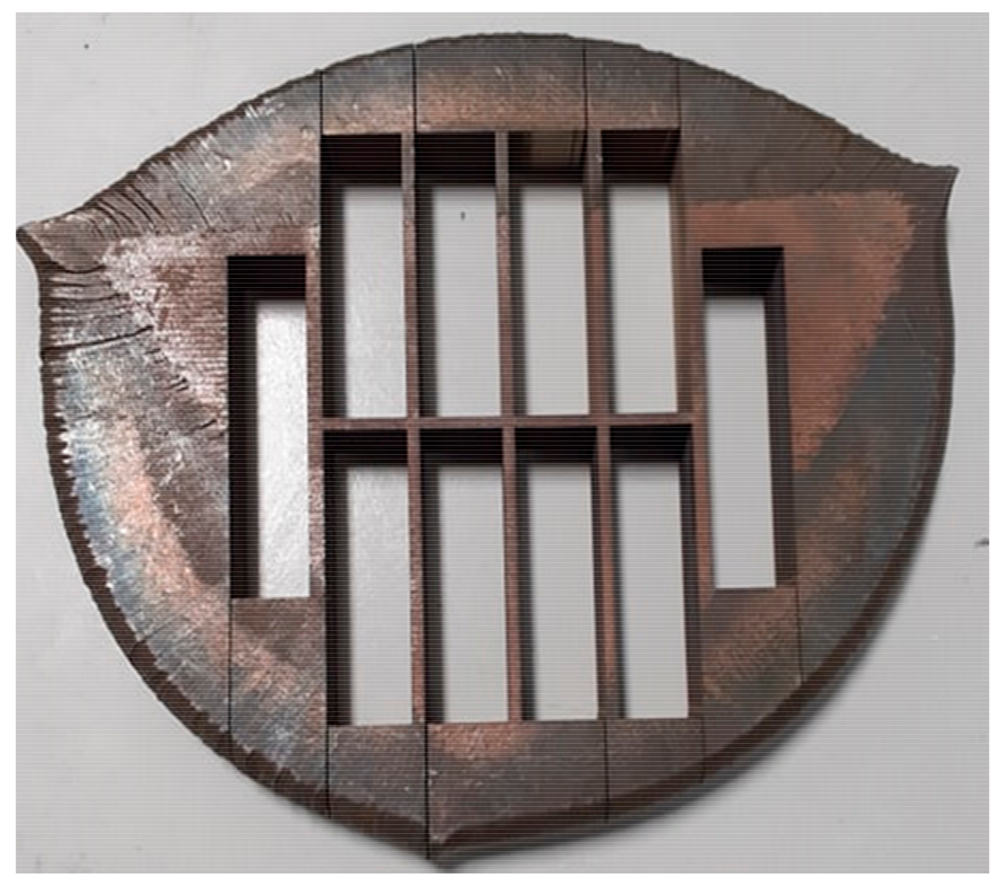
Titanium Metals Corporation (TIMET) produce ingots of the Ti-407 alloy, through the employment of electron beam, single-melting (EBSM), utilising a cold hearth furnace [8]. A proprietary sequence of thermomechanical processing was carried out to produce component representative “pancake” forgings for this work. Blanks were extracted for mechanical assessment from the central regions of each pancake, deliberately avoiding the material extremities (Figure 1).
The relevant temperature of solution treatment to produce a bi-modal α + β microstructural form, containing 30–40% volume fraction of primary alpha (αp), was determined through heat treatment trials. Guidance was offered from early stage research development trials [2], where the optimum fatigue performance was obtained when the alloy contained this specific volume fraction. Whilst an even distribution of αp within a lamellar matrix is known to provide a refinement of the grain size, encourage increased tensile plasticity, and inhibit regions containing a common, crystallographic orientation [8], the αp content must be limited, in order to retain mechanical ductility and avoid element partitioning. The trade off is a lower ultimate tensile strength for lamellar dominated microstructures, also resulting in a decrease in fatigue strength [9].
Microstructure experiments were conducted in an electric furnace. Two calibrated N type thermocouples remained in intimate contact with the 15 mm cubes throughout these trials, which employed three different solution treatment temperatures: 820 °C; 840 °C and 860 °C. For reference, the β transus for the alloy has been measured as 877 °C [6]. Microstructures generated at each temperature are illustrated in Figure 2, together with image analysis to identify αp grains (highlighted in red). The specimens subjected to solution heat treatment at 840 °C for two hours, followed by air cooling, produced the desired 30% αp volume fraction, identified using an image analysis thresholding technique. The average αp grain diameter was 12 µm and average width of the secondary α laths was measured at 0.65 µm. This solution heat treatment, followed by an 8 h aging process at 500 °C, was subsequently applied to all Ti-407 specimen blanks intended for plain specimen fatigue testing.
Specimen blanks intended for fatigue crack growth experiments also incorporated the optimised 840 °C/air cooled heat treatment described above, as well as additional solution treatments at 820 °C and 870 °C, each for 2 h. In addition, two different cooling rates (designated “fast” and “slow”) were employed, to control the average width of the secondary α laths. The relatively fast air cooling again produced lath widths at 0.65 μm, whilst this was increased to 0.9 μm under slow cooling in a vermiculite media. The difference in secondary α lath width, associated with the 840 °C, 30% αp microstructure, is demonstrated in Figure 3.
2.2. Specimen Design and Manufacture
Subsequent to heat treatment, the blanks were machined into plain cylindrical specimens suitable for tensile and fatigue experiments, plus corner crack fatigue, crack growth specimens, with a 5 × 5 mm square section, using conventional computer encoded controlled turning and milling (Figure 4a,b respectively).
2.3. Mechanical Test Procedures
All mechanical testing was conducted at a laboratory temperature of 22 °C, and followed appropriate international standards for fatigue and fatigue crack growth experimentation [10,11,12]. These test procedures were fully consistent with our previous practise, applied to Ti-834 specimens, used for subsequent comparison to the Ti-407 data.
2.3.1. Load-Controlled Fatigue Tests
A vibrophore style test machine, resonating under a 100Hz sinusoidal waveform and R = 0 load ratio, was employed for high-cycle fatigue (HCF) experiments.
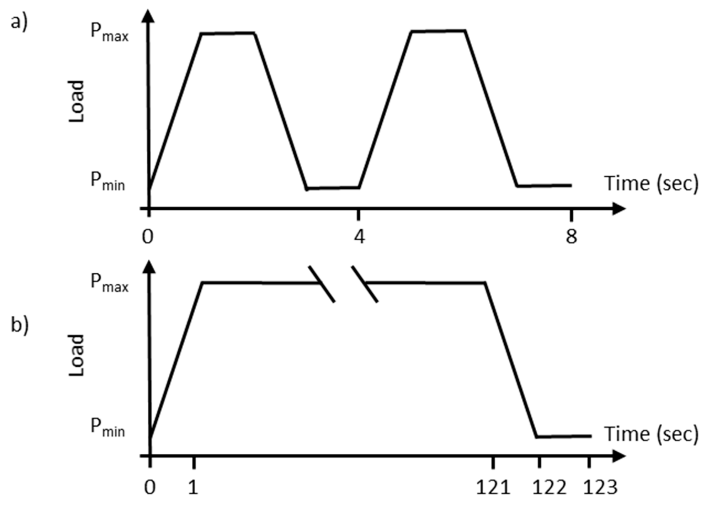
Various servo-hydraulic test machines were used for low-cycle fatigue (LCF) tests, applying a 15 cycle per minute trapezoidal waveform, comprising one second linear rise and fall ramps, with a one second hold at both peak and minimum load, again under R = 0.
Servo hydraulic test rigs were also employed for the dwell fatigue tests, incorporating a 120s hold at peak stress and 1s offload. Schematic diagrams to define the LCF and dwell waveforms are included as Figure 5. Complete rupture of the specimen was achieved in all specimens, i.e., no “run-outs” are reported.
2.3.2. Strain Controlled LCF testing
Results from a single strain controlled fatigue test are reported to define the cyclic stress–strain behaviour of Ti-407 at room temperature. A trapezoidal, R = 0 waveform was applied under the control of a side-mounted strain gauge bridge extensometer. Linear rise and fall ramps were fixed at a strain rate of 0.5/s, with a one second hold imposed at peak and minimum strain. Fatigue cycling was deliberately initiated at a relatively low strain amplitude (εmax = 0.4%) whilst the response in peak and minimum stress were recorded each cycle. The maximum stress achieved at the end of this period was recorded as the stabilised stress condition for that particular magnitude of cyclic strain. The peak cyclic strain was increased after successive periods of 10,000 cycles, utilising strain step increments of 0.05%. A cyclic stress–strain curve (CSSC) was generated in this fashion and compared to the monotonic stress–strain curve (MSSC), defined by a standard monotonic tensile test (up to 1% strain).
2.3.3. Fatigue Crack Growth Tests
A pulsed direct current potential drop (DCPD) system was employed to automatically monitor constant amplitude, load-controlled crack growth in the corner crack specimens, utilising a constant current set to 10A [13]. Platinum wires were welded either side of the starter slit, as close as possible to the specimen edge and the plane of eventual crack propagation. Corner cracks were generated under a 15 cpm trapezoidal waveform, with peak stress varying between 300 and 450 MPa. Load ratios of R = 0.05 and R = 0.7 were employed. Tests were typically terminated at a maximum final crack length of approximately 2 mm, correlating to a crack length divided by specimen width ratio (a/W) of 0.4 in the 5 × 5 mm square section. On completion of crack growth, the specimens were heat tinted in a furnace at 550 °C for 1 h, in order to oxidise the crack, followed by nominal fatigue loading at room temperature to rupture the specimen. This allowed measurement of the final quarter circular crack profile. Employing a linear calibration relationship, based on initial and final length/voltage readings, measured crack voltages were converted to crack length, to support crack length versus cycles (a vs N), and crack growth rate as a function of cyclic stress intensity (da/dN vs ΔK) analysis. A metallographic section was prepared from selected specimens (on one side face prior to rupture), orientated orthogonal to the plane of crack growth, to observe the crack path in relation to the local microstructure.
3. Results
3.1. HCF, LCF and Dwell Fatigue
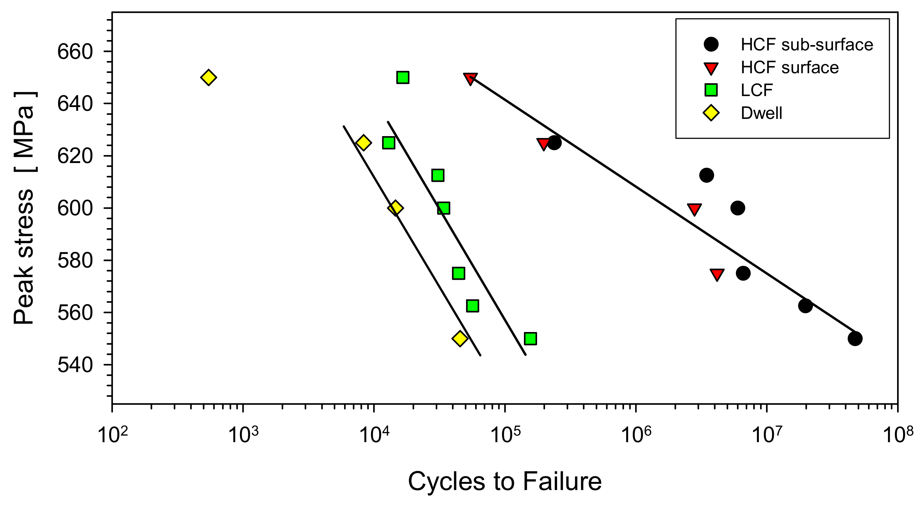
The combined HCF, LCF and dwell fatigue data generated from Ti-407 are plotted in Figure 6, with least squares, best fit trend lines superimposed to the LCF and HCF data sets. A parallel line has been superimposed through the dwell data points by eye, ignoring the test at 650 MPa which displayed evidence of bulk plasticity and a severe reduction in area. By performing tests over an identical range of applied peak stress conditions, (i.e., individual tests were performed across the range 500 and 650 MPa), the relatively strong response under HCF loading was emphasised, relative to LCF performance and, in turn, dwell behaviour.
Detailed characterisation of the fracture surfaces demonstrated that the individual HCF specimens failed from an assortment of subsurface and surface initiation sites. This behaviour has been demarcated in Figure 6 and typical examples are illustrated under low magnification (Figure 7). The failures that originated sub-surface were easily identified by eye, with a circular shaped, bright halo, formed during sub-surface crack propagation, effectively under a vacuum environment. Once the crack broke through to the surface, subsequent oxidation of the fracture surface induced a relatively dull appearance. Clusters of quasi-cleavage facets were invariably revealed at the centre of the sub-surface halo or at the gauge surface periphery, marking the precise site of fatigue crack initiation, Figure 7. At high magnification (under scanning electron microscope inspection), the facets took on an elongated form, corresponding to fractures occurring through individual αp grains. Immediately adjacent to the facet clusters, regions of greater ductile appearance were evident, representing failure through the juxtaposed regions of transformed α/β microstructure. Any difference in appearance between the two facet clusters illustrated in Figure 8 is purely an artefact of the viewing angle relative to the electron beam, thus helping to emphasise the inclination of the sub-surface examples (i.e., neither example displayed evidence of local abrasion or crack closure).
Similar facets were detected in the LCF and dwell fractures, however, in both cases, all specimens failed from surface locations. A distinct difference was noted in the inclination of the facets under HCF loading, as opposed to LCF and dwell. Detailed quantitative tilt fractography (QTF), following the techniques described by Sinha and Themelis [14,15], was performed, to measure the inclination of initiating facets, relative to the plane orthogonal to the loading axis. Table 1 collates such data, indicating that facets under LCF and dwell waveforms tended to be orientated near orthogonal to the applied tensile stress axis. In contrast, facets generated under HCF conditions were consistently inclined at higher angles, some as high as 60°. Additional measurements are also quoted, taken from Ti-6-4 pancake-derived specimens tested during this same research campaign.
3.2. Cyclic Stress–Strain Response
The cyclic stress–strain curve defined from the incremental strain controlled fatigue test is compared to the monotonic stress–strain curve (plotted up to 1% absolute strain) in Figure 9. Compared to the monotonic yield strength, at approximately 540 MPa, plastic yield was induced at a relatively lower stress magnitude of 420 MPa under cyclic conditions. This cyclic softening behaviour is a well established property of many α + β titanium alloys at room temperature [16]. Across the range of incremental peak strains assessed, the alloy was approximately 100 MPa weaker under cyclic loading, compared to the equivalent monotonic response.
3.3. Fatigue Crack Growth.
The combined fatigue crack growth data measured from Ti-407 specimens are plotted in Figure 10. This illustrates a relatively consistent response for cracks growing under the Stage II Paris regime, without sensitivity to solution heat treatment temperature, associated microstructure, or mean stress. Indeed, the data set can be represented by a single power law fit, with the Paris coefficients m = 2.934 and C = 5 × 10⁻¹¹, respectively.
The preparation and inspection of metallographic sections prepared on an orthogonal plane to the crack growth confirmed its insensitivity to local microstructure. A typical example, Figure 11, demonstrates that the crack tip interacts with the αp grains in both transgranular and intergranular mechanisms. Growth through the transformed regions was also varied, with both translamellar and interlamellar modes evident. A minor degree of crack bifurcation was evident, however, the macroscopic plane of cracking was generally flat and perpendicular to the applied tensile stress axis. Local electron back-scatter diffraction measurements, conducted along the wake of the crack, demonstrated that where the basal plane of αp grains was close to co-planar with the plane of crack growth then the crack would seek a transgranular pathway, consistent with previous studies involving the alloy Ti-834 [17]. In contrast, if the αp grains presented either pyramidal or prismatic planes, co-planar to crack growth, then the crack would tend to extend in the intergranular fashion.
4. Discussion
The present research has demonstrated a superior fatigue strength in forged Ti-407 under high frequency HCF loading, compared to the 15 cpm LCF and 2 min dwell waveforms. Indeed, the difference between HCF and dwell response, in terms of fatigue life at any given level of applied peak stress, consistently exceeds two orders of magnitude across the range of stress conditions employed. The HCF strength displayed by Ti-407 may be considered high when compared to the UTS for the same alloy. It is encouraging to report that this superior HCF strength in Ti-407 is not offset by a reduction in ductility [2], giving the alloy a broad appeal for high-performance engineering applications. It should be emphasised that the Ti-407 material employed for the present study could be further optimised, via different thermo-mechanical processing routes. Therefore, the present microstructural condition, produced via pancake forging of billet material and laboratory heat treatment, may not be consistent with that produced in real engineering components.
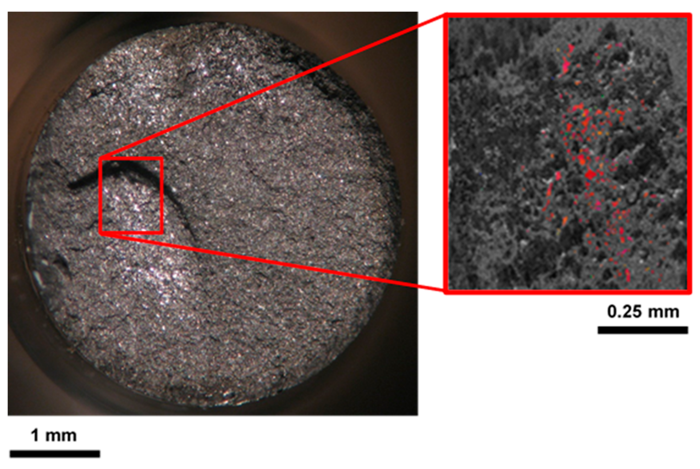
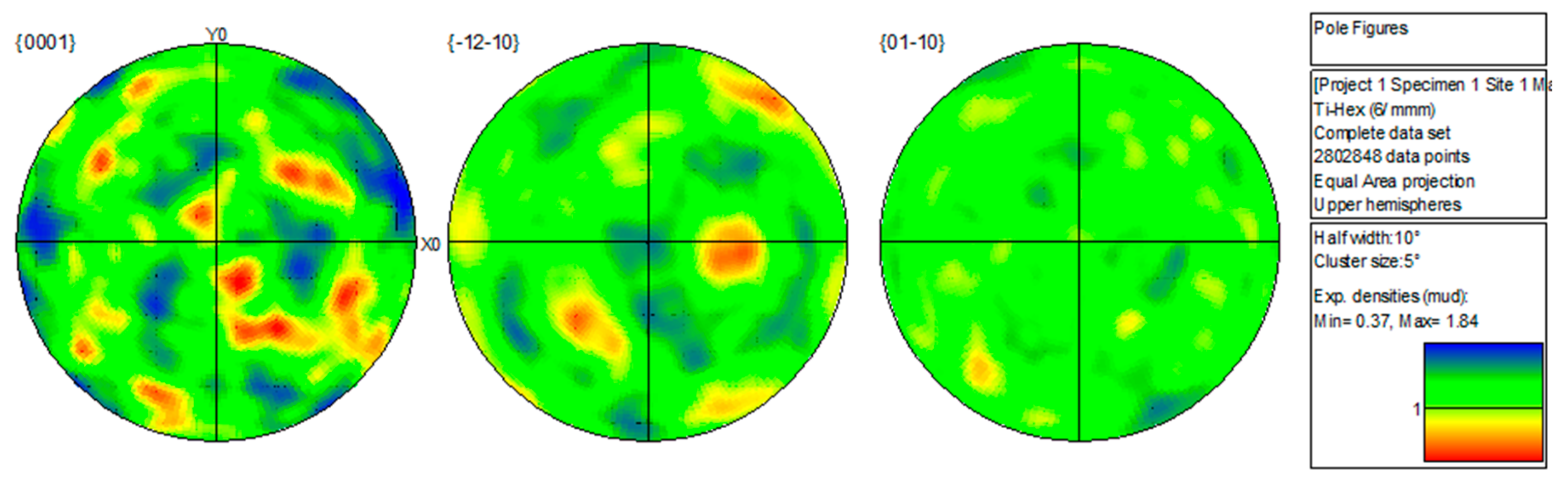
In a wider context, this study has also contributed to the fundamental understanding of dwell fatigue in α + β and near α titanium alloys. After noting the predominance of quasi-cleavage facets at the epicentre of both surface and sub-surface crack initiation sites in all Ti-407 specimens, metallographic sections were taken immediately below the fracture surface of selected specimens. The polished plane was prepared approximately 5 mm sub-fracture, using standard grinding and etch techniques. EBSD measurements were taken, to generate crystallographic orientation maps extending across the entire specimen gauge section, exemplified by Figure 12. This represents a montage of 70 individual small area scans of approximately 500 × 500 μm, conducted with a step size between 2–3 µm. Figure 13 shows the pole figures relating to this section, thus representing a nominal plane parallel to the forging axis and perpendicular to the tensile loading axis during subsequent mechanical assessment. A moderate basal plane texture was evident, with a preferred basal pole orientation of x3.6 random. The -12–10 and 01–10 maps also indicate a preferential axis of rotation of individual αp grains. Being displaced from the plane of fracture by approximately 5 mm, these sections were not considered as a means for explaining the precise failure mechanism, responsible for fracture in specific specimens. However, the microstructures and textures revealed were highly reminiscent of those previously reported for a forged disc variant of the near-α alloy Ti-834, previously described as an archetypal dwell sensitive alloy [18].
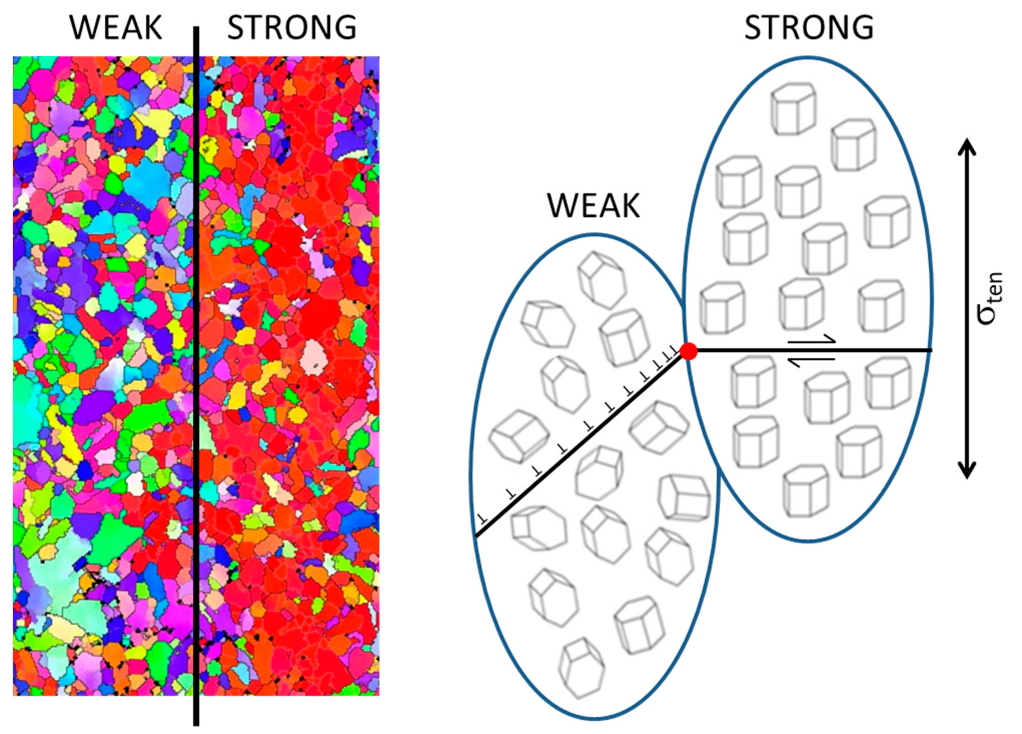
The trend in fatigue strength relative to waveform frequency, displayed by Ti-407, demonstrates the effect of time-dependent deformation on crack initiation life. A similar trend was reported by this laboratory for the forged disc variant of the alloy Ti-834 [19]. As confirmed, both alloys incorporate regions within the microstructure, where individual αp grains take a common basal plane orientation. These macro-zones can then act as the controlling mechanical units within the bulk material. Within regions where the grains are orientated with the basal plane approximately perpendicular to the applied tensile stress, a relatively strong response will be generated. This is a consequence of the basal plane, the preferred slip system in the hexagonal α phase of titanium at room temperature, being poorly orientated for shear and dislocation glide (i.e., offering low Schmid factors). Neighbouring regions, either with randomly orientated αp grains or, if textured, with predominantly inclined αp grains, would deform relatively easily. Here, grains could also promote prismatic or pyramidal slip in these weaker regions. Slip could be easily accommodated between the individual neighbouring grains with common crystal orientation, providing relatively long slip lengths. However, at the boundary between the adjacent regions, dislocation pile ups would be generated. This proposed mechanism essentially mirrors the Stroh redistribution model [20], previously adopted by Evans and Bache [21] to explain quasi-cleavage facets formed in large grain near-α alloys, but now considered on a regional, macro-zone scale. A revised schematic representation of the redistribution model is illustrated in Figure 14 and compared with a nominal α + β microstructure, illustrating neighbouring regions of random (weak) and common (strong) grain orientation distributions. The model predicts that the degree of shear and tensile stress induced by dislocation pile ups at the boundary between weak and strong regions is directly proportional to the slip band length. Hence, the larger the grain or macro-zone size, the greater the propensity for stress redistribution and dwell sensitivity.
Clearly, the dislocation glide mechanism behind stress redistribution and ultimately facet formation, often referred to as cold creep, would be encouraged by the time on load. Hence, the relatively weak response displayed by Ti-407 under 2 min dwell conditions. In the absence of dwell time on load, a classical “stage I” fatigue crack initiation style mechanism [22] would dominate, with the basal facets inclined to the tensile loading. This has been confirmed during the current investigation by quantitative tilt fractography measurements taken from the facets formed in the Ti-407 HCF specimens. Table 1 illustrated the average tilt angle, whether measured from surface or sub-surface initiation sites, was approximately 45° under the 100 Hz HCF waveform. Measurements taken from additional Ti-6-4 HCF specimens confirm the mechanism is consistent across different alloys. This contrasts with the near orthogonal orientation of the clustered facets in LCF and dwell failures in Ti-407, plus the numerous examples previously characterised in macro-zones in Ti-834 disc material [18], with new examples from the latter alloy presented in Figure 15. Limited EBSD measurements, taken directly from facets on the fracture surfaces of Ti-407 specimens, have also detected a basal plane form. The time-dependent control of facet orientation is consistent with the long-standing anecdotal evidence generated by Evans, investigating dwell behaviour for the Royal Aircraft Establishment, Farnborough, who also reported that orthogonal orientated facets were generated under cyclic, dwell and creep experiments [23], but not under monotonic tensile tests to rupture.
The formation of quasi-cleavage facets is not exclusive to dwell behaviour. They will still persist even under high frequency HCF loading simply because of the fundamental weakness of the basal plane within the hexagonal grain crystal structure. What is unique under dwell failure, is the orientation of the facets being approximately orthogonal to the applied tensile stress. The time-dependent stress redistribution mechanism is essential to induce slip on the poorly orientated basal planes and, later, in contribution with the applied tensile loading, progressively opening the facet to form an embryonic fatigue crack. This early-stage discontinuity, now forming on a Mode I plane, can support crack extension, assuming the critical combination of applied stress and crack size are exceeded, i.e., ΔKapplied exceeds the fatigue crack growth threshold value ΔKth.
The presence of macrozones within the developmental Ti-407 pancake forgings was pertinent to the dwell-sensitive fatigue response, illustrated by Figure 6. However, through an understanding of the dwell phenomenon, optimisation of thermo-mechanical process routes to generate a random distribution of αp grains, without a strong micro-texture, can eliminate dwell sensitivity in this class of alloy [24]. This is further illustrated here, utilising fatigue data generated from a bar stock variant of Ti-834 (Figure 16), tested under waveforms of various frequency, from 2 minute dwell, through 15 cpm trapezoid, to 1 Hz, 10 Hz and 100 Hz sine. Relatively consistent fatigue strength is measured independent of waveform frequency, with the scatter in fatigue life no greater than a single order of magnitude at any applied stress level. EBSD analysis of the bar stock variant confirmed an even distribution in grain size and orientation (Figure 17 and Figure 18). Therefore, in the absence of macrozones or a large grain size, this class of alloy could potentially achieve the optimum fatigue performance, normally defined under HCF conditions, through the avoidance of redistribution between weak and strong regions.
The marked difference between monotonic and cyclic constitutive behaviour, demonstrated in Figure 9, helps to explain the susceptibility to cyclic damage on the bulk scale. It can be assumed that all load-controlled fatigue tests, performed at a peak stress greater than the cyclic yield condition of 420 MPa, would experience considerable “ratchetting” in strain, and previous studies have shown the propensity for strain accumulation under dwell, as opposed to regular, fatigue cycles [25]. This effect would be enhanced by “cold creep” and the relevant time spent at peak stress per fatigue cycle. Three stress conditions employed during the current fatigue matrix are considered in Table 2, to demonstrate the amount of time spent at peak stress under the three HCF, LCF and dwell scenarios. For the HCF waveform, the time spent above 90% of the applied sinusoidal stress has been assumed to impart the relevant damage. Clearly, the number of cycles required to accumulate the critical bulk strain is reduced under dwell loading.
The generation of quasi-cleavage facets and early-stage cracking under dwell fatigue loading effectively reduces the cyclic initiation life. The remaining fraction of the total life, spent propagating the crack to a critical dimension that induces tensile overload and final fracture, would presumably be relatively small. Regardless, it was encouraging to note during the present study on Ti-407 that a range of microstructures, deliberately assessed to consider the potential effects of cooling rate and solution treatment temperature on damage tolerance behaviour, demonstrated no sensitivity to fatigue crack growth of stage II or “long” cracks across the range of the ΔK assessed (Figure 10). This is despite the mechanical application of two widely separated R ratio values (R = 0.01 and R = 0.7) and the deliberate inclusion of six varying microstructural conditions, including notable variations in α lath width. This increases confidence in future damage-tolerant-based lifting methodologies, applied to Ti-407 components, particularly for relatively large or thick section geometries, where cooling rates after heat treatment may be difficult to control. The high magnification image of local crack mechanisms, illustrated in Figure 11, demonstrates that the crack tip interacts with the primary α grains and transformed β regions in a random fashion.
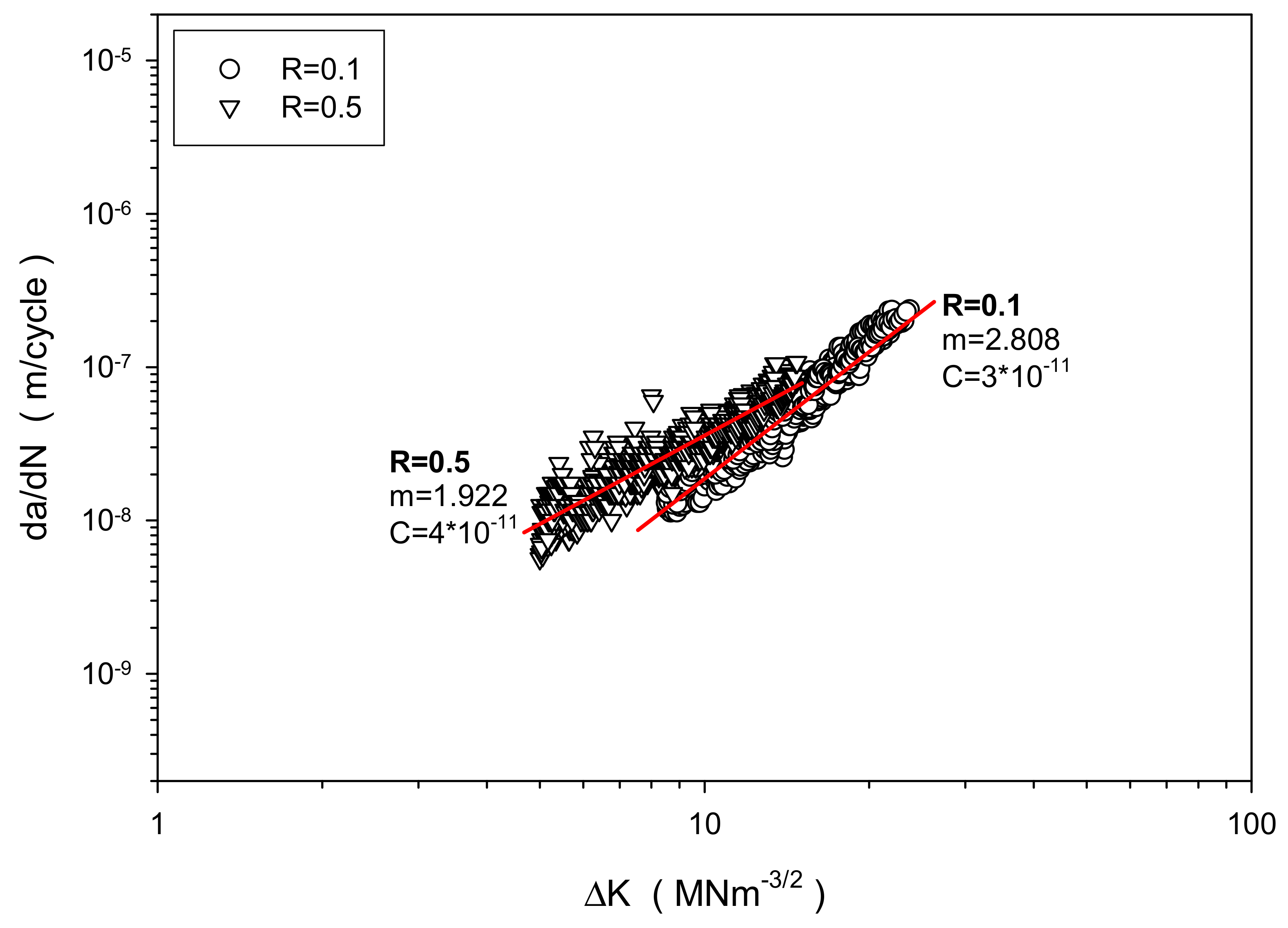
The consistency of the Ti-407 fatigue crack growth data is emphasised by comparing to a hitherto unreported database of similar experiments performed in the Swansea laboratory, employing the same Ti-834 bar stock material described above in terms of fatigue behaviour (i.e., processed to provide a bimodal microstructure containing 15% primary α in a transformed β matrix with a regular α lath size). Ten individual corner crack tests were deliberately repeated at the exact same room temperature loading conditions at R = 0.1, followed by eight repeats at the same maximum stress level at a high mean stress of R = 0.5 [26], with the data plotted in Figure 19.
Despite the tight control on microstructure for the Ti-834 specimens, a natural degree of experimental scatter was defined when combining the individual test data for a given R ratio, and distinct differences in performance were defined, according to the respective low and high mean stress conditions applied. By comparing the “goodness of fit” r2 values for the Ti-834 datasets to those achieved from the combined Ti-407 data, Table 3, the performance of the Ti-407 alloy can be viewed as highly reliable.
5. Conclusions
In conclusion, the novel α + β titanium alloy Ti-407 has shown good HCF strength, relative to yield properties, and provided better HCF strength compared to previous forms of Ti-6-4 assessed by this laboratory [27], without compromising ductility, machinability and manufacturing properties. The relatively high HCF strength of Ti-407 can be viewed as an encouraging outcome for what is recognised as a comparatively low static strength alloy. Consistent fatigue crack growth behaviour was measured for Ti-407 microstructures containing a range of secondary α lath morphologies. Other findings from this investigation, key to a general understanding of the “cold dwell” phenomenon, include:
- That regions of common crystallographic orientations (or macro-zones) persist in Ti-407 after selected forging operations employed to process pancakes from billet.
- The presence of macro-zones in Ti-407 appears to induce a sensitivity to dwell fatigue, in a similar fashion to that previously identified in Ti-834 disc material.
- That fatigue crack initiation under dwell cycles is controlled by stress redistribution between hard and soft regions, ranging in scale from adjacent grains to relatively extensive zones of common crystallographic orientation.
- That quasi-cleavage facets developed under LCF and dwell waveforms tend to be orientated near perpendicular to the applied tensile stress axis.
- That extremes of loading condition where time-dependent deformation is avoided (HCF and monotonic tension) may still generate quasi-cleavage facets, but, under these circumstances, they are inclined to the tensile stress axis.
Author Contributions
Project conceptualization, M.B. and M.T.; funding acquisition, M.B and M.T.; experimental investigation and methodology was addressed by all co-authors; student supervision, M.B., H.D. and M.T.; writing–original draft, M.B.; writing–review and editing, M.B., W.D. and I.B.-P.
Funding
The current research was funded under the EPSRC Rolls-Royce Strategic Partnership in Structural Metallic Systems for Gas Turbines (EPSRC grants EP/H500383/1 and EP/H022309/1).
Acknowledgments
Mechanical tests were performed at Swansea Materials Research & Testing Ltd. (SMaRT). The provision of materials and supporting information from TIMET UK is gratefully acknowledged.
Conflicts of Interest
The authors declare no conflict of interest.
References
- Wood, R.; Favor, R. Titanium Alloys Handbook; Battelle Columbus Labs Ohio Metals and Ceramics Information Center: Columbus, OH, USA, 1972. [Google Scholar]
- James, S.; Kosaka, Y.; Thomas, R.; Garratt, P. Timetal 407: A Titanium Alloy to Enable Cost Reduction. In Proceedings of the 13th World Conference on Titanium; Venkatesh, V., Pilchak, A.L., Allison, J.E., Ankem, S., Rodney, B., Christodoulou, J., Fraser, H.L., Imam, M.A., Kosaka, Y., Henry, J.R., et al., Eds.; The Minerals, Metals & Materials Society: Pittsburgh, PA, USA, 2016. [Google Scholar]
- Siekmann, H. How to machine titanium. Tool Eng. 1995, 34, 78–82. [Google Scholar]
- Komanduri, R.; Reed, W. Evaluation of carbide grades and a new cutting geometry for machining titanium alloys. Wear 1983, 92, 113–123. [Google Scholar] [CrossRef]
- Ezugwu, E.O.; Wang, Z.M. Titanium alloys and their machinability. J. Mater. Process. Technol. 1997, 68, 262–274. [Google Scholar] [CrossRef]
- Rahman, M.; Wong, Y.S.; Zareena, R. Machinability of Titanium Alloys. JSME Int. J. Ser. C 2003, 46, 107–115. [Google Scholar] [CrossRef]
- Lütjering, G. Influence of processing on microstructure and mechanical properties of (α + β) titanium alloys. Mater. Sci. Eng. A 1998, 243, 32–45. [Google Scholar] [CrossRef]
- Wu, G.Q.; Shi, C.L.; Sha, W.; Sha, A.X.; Jiang, H.R. Effect of microstructure on the fatigue properties of Ti-6Al-4V titanium alloys. Mater. Des 2013, 46, 668–674. [Google Scholar] [CrossRef]
- Wegmann, G.; Lutjering, G.; Alberecht, J. Improvement of the properties of (α + β) titanium castings by modification of the lamellar structure. Titan. ’95 Sci. Technol. 1996, 895–901. [Google Scholar]
- Methods of Fatigue Testing-Part 1: Guide to General Principles, 93rd ed.; BSI: London, UK, 1993.
- Metallic Materials. Fatigue Testing. Axial-Strain-Controlled Method, 2nd ed.; BSI: London, UK, 2017.
- Juan, P.-I. Standard Test Method for Measurement of Fatigue Crack Growth Rates; ASTM International: West Conshohocken, PA, USA, 2014. [Google Scholar]
- Mom, A.J.A. Revised Working Document for the AGARD Cooperative Test Programme on Titanium Alloy Disc Engine Material, Appendix A. AGARD Engine Disc Cooperative Test Programme; Report NLR TR L; NLR: Amsterdam, The Netherlands, 1986. [Google Scholar]
- Sinah, V.; Mills, M.; Williams, J. Determination of crystallographic orientation of dwell-fatigue fracture facets in Ti-6242 alloy. J. Mater. Sci. 2007, 42, 8334–8341. [Google Scholar] [CrossRef]
- Themelis, G.; Chikwembani, S.; Weertman, J. Determination of the orientation of Cu Bi grain boundary facets using a photogrammetric technique. Mater. Characterisation 1990, 24, 27–40. [Google Scholar] [CrossRef]
- Smith, R.W.; Hirschberg, M.H.; Manson, S.S. Fatigue Behaviour of Materials under Strain Cycling in Low and Intermediate Life Range; (Technical Note D-157:); National Aeronautics and Space Administration: Washington, DC, USA, 1963. [Google Scholar]
- Wilson, R.J.; Randle, V.; Evans, W.J. The influence of the Burgers relation on crack propagation in a near α-titanium alloy. Phil. Mag. 1997, 76A, 471–480. [Google Scholar] [CrossRef]
- Germain, L.; Bache, M.R. Crystallographic texture and the definition of effective structural unit size in titanium products. In Ti-2007 Science and Technology; Niinomi, M., Akiyama, S., Hagiwara, M., Ikeda, M., Maruyama, K., Eds.; The Japan Institute of Metals: Sendai, Japan, 2007; pp. 953–956. [Google Scholar]
- Bache, M.R.; Cope, M.; Davies, H.M.; Evans, W.J.; Harrison, G. Dwell sensitive fatigue in a near alpha titanium alloy at ambient temperature. Int. J. Fatigue 1997, 19, S83–S88. [Google Scholar] [CrossRef]
- Stroh, A.N. The formation of cracks as a result of plastic flow. Proc. R. Soc. Lond. Ser. Math. Phys. Sci. 1954, 223, 404–414. [Google Scholar]
- Evans, W.J.; Bache, M.R. Dwell-sensitive fatigue under biaxial loads in the near-alpha titanium alloy IMI685. Int. J. Fatigue 1994, 16, 443–452. [Google Scholar] [CrossRef]
- Forrest, P.G. Fatigue of Metals; Elsevier: Amsterdam, The Netherlands, 2013. [Google Scholar]
- Evans, W.J. Optimising mechanical properties in α + β titanium alloys. Mater. Sci. Eng. 1998, 243, 89–96. [Google Scholar] [CrossRef]
- Bache, M.R.; Thomas, M. Alloy development and optimisation informed by an understanding of cold dwell fatigue sensitivity. In Proceedings of the Ti-2019: 14th World Conference on Titanium, Nantes, France, 10–14 June 2019; Inovar Communications Ltd.: Shrewsbury, UK, 2019. [Google Scholar]
- Bache, M.R. A review of dwell sensitive fatigue in titanium alloys: the role of microstructure, texture and operating conditions. Int. J. Fatigue 2003, 25, 1079–1087. [Google Scholar] [CrossRef]
- Harriss, C.A. A comprehensive study of metal fatigue as a stochastic process in gravity die-cast LM25 aluminium and Timetal 834 titanium alloys. Ph.D. Thesis, University of Wales, Swansea, UK, 2000. [Google Scholar]
- Davey, W.; Bache, M.R.; Davies, H.M.; Thomas, M. Fatigue Performance of the Novel Titanium Alloy Timetal 407. In Proceedings of the MATEC Web of Conferences, Poitiers, France, 27 May–1 June 2018; EDP Sciences: London, UK, 2018. [Google Scholar]
Figure 1.
Specimen blank extraction from a pancake forging.

Figure 2.
Bi-modal microstructures generated under three solution heat treatment temperatures; (a) 820 °C, (b) 840 °C, (c) 860 °C. Scanning electron microscope imaging (left), corresponding image analysis (right).
Figure 2.
Bi-modal microstructures generated under three solution heat treatment temperatures; (a) 820 °C, (b) 840 °C, (c) 860 °C. Scanning electron microscope imaging (left), corresponding image analysis (right).

Figure 3.
Control of secondary α lath width under 840 °C solution heat treatment. (a) “fast” air cooling, (b) “slow” vermiculite cooling.
Figure 3.
Control of secondary α lath width under 840 °C solution heat treatment. (a) “fast” air cooling, (b) “slow” vermiculite cooling.

Figure 4.
(a) Plain cylindrical tensile/fatigue specimen, (b) Fatigue crack growth specimen. All dimensions are in mm.
Figure 4.
(a) Plain cylindrical tensile/fatigue specimen, (b) Fatigue crack growth specimen. All dimensions are in mm.

Figure 5.
(a) Low-cycle fatigue (LCF) waveform, (b) Dwell waveform.

Figure 6.
High fatigue cycle (HCF), LCF and dwell fatigue data for Ti-407.

Figure 7.
Examples of surface (left) and sub-surface (right) crack initiation sites in Ti-407 (scanning electron microscope inspections).
Figure 7.
Examples of surface (left) and sub-surface (right) crack initiation sites in Ti-407 (scanning electron microscope inspections).

Figure 8.
Facet clusters initiating surface (left) and sub-surface (right) failure. Both of these specimens were tested under a peak stress of 575MPa and HCF waveform.
Figure 8.
Facet clusters initiating surface (left) and sub-surface (right) failure. Both of these specimens were tested under a peak stress of 575MPa and HCF waveform.

Figure 9.
Stress–strain behaviour measured under monotonic (MSSC) and cyclic (CSSC) loading.

Figure 10.
Combined fatigue crack growth data for Ti-407, representing six different microstructures and two R ratios.
Figure 10.
Combined fatigue crack growth data for Ti-407, representing six different microstructures and two R ratios.

Figure 11.
Local crack/microstructure interactions in Ti-407 (crack growth from left to right).

Figure 12.
EBSD orientation map, obtained 5 mm below the fracture plane of a nominal Ti-407 specimen. The plane illustrated was parallel to the forging axis and perpendicular to the mechanical testing axis.
Figure 12.
EBSD orientation map, obtained 5 mm below the fracture plane of a nominal Ti-407 specimen. The plane illustrated was parallel to the forging axis and perpendicular to the mechanical testing axis.

Figure 13.
EBSD pole figures associated with Figure 12.
Figure 13.
EBSD pole figures associated with Figure 12.

Figure 14.
The Evans–Bache model, applied to weak and strong regions made up of multiple grains, with random basal and common orientations, respectively.
Figure 14.
The Evans–Bache model, applied to weak and strong regions made up of multiple grains, with random basal and common orientations, respectively.

Figure 15.
EBSD detection of facets exposed by fatigue failure, correlating to a macro-zone in Ti-834 disc material.
Figure 15.
EBSD detection of facets exposed by fatigue failure, correlating to a macro-zone in Ti-834 disc material.

Figure 16.
HCF, LCF and dwell fatigue data for Ti-834 bar stock material.

Figure 17.
EBSD orientation map obtained from Ti-834 bar stock material.

Figure 18.
EBSD pole figures associated with Figure 17.
Figure 18.
EBSD pole figures associated with Figure 17.

Figure 19.
Experimental scatter from repeat fatigue crack growth tests performed on Ti-834 bar stock material.
Figure 19.
Experimental scatter from repeat fatigue crack growth tests performed on Ti-834 bar stock material.


Table 1.
QTF measurements of fatigue initiating facets.
| Loading Regime | Facet Inclination (o) | Alloy |
|---|---|---|
| HCF | 37 | Ti-407 |
| HCF | 61 | Ti-407 |
| HCF | 39 | Ti-407 |
| HCF | 26 | Ti-407 |
| LCF | 11 | Ti-407 |
| LCF | 14 | Ti-407 |
| Dwell | 15 | Ti-407 |
| HCF | 37 | Ti-6-4 |
| HCF | 33 | Ti-6-4 |
Table 2.
Time at maximum stress under different waveform conditions.
| Peak Stress (MPa) | HCF (Hrs) | LCF (Hrs) | Dwell (Hrs) |
|---|---|---|---|
| 650 | 0.02 | 4.62 | 18.23 |
| 600 | 1.67 | 9.48 | 486.67 |
| 550 | 13.12 | 43.50 | 1513.66 |
Table 3.
Power law coefficients for the combined Ti-407 fatigue crack growth data compared to two data sets representing Ti-834 bar stock material at R = 0.1 and R = 0.5.
Table 3.
Power law coefficients for the combined Ti-407 fatigue crack growth data compared to two data sets representing Ti-834 bar stock material at R = 0.1 and R = 0.5.
| Parameter | Ti-407 (All Data) | Ti-834 (R = 0.1) | Ti-834 (R = 0.5) |
|---|---|---|---|
| m (slope) | 2.934 | 2.808 | 1.922 |
| C (intercept) | 5 × 10⁻¹¹ | 3 × 10⁻¹¹ | 4 × 10⁻¹¹ |
| r2 (goodness of fit) | 0.961 | 0.954 | 0.908 |
© 2019 by the authors. Licensee MDPI, Basel, Switzerland. This article is an open access article distributed under the terms and conditions of the Creative Commons Attribution (CC BY) license (http://creativecommons.org/licenses/by/4.0/).
Share and Cite
MDPI and ACS Style
Bache, M.; Davies, H.; Davey, W.; Thomas, M.; Berment-Parr, I. Microstructural Control of Fatigue Behaviour in a Novel α + β Titanium Alloy. Metals 2019, 9, 1200. https://doi.org/10.3390/met9111200
AMA Style
Bache M, Davies H, Davey W, Thomas M, Berment-Parr I. Microstructural Control of Fatigue Behaviour in a Novel α + β Titanium Alloy. Metals. 2019; 9(11):1200. https://doi.org/10.3390/met9111200
Chicago/Turabian StyleBache, Martin, Helen Davies, William Davey, Matthew Thomas, and Iain Berment-Parr. 2019. "Microstructural Control of Fatigue Behaviour in a Novel α + β Titanium Alloy" Metals 9, no. 11: 1200. https://doi.org/10.3390/met9111200
Note that from the first issue of 2016, this journal uses article numbers instead of page numbers. See further details here.