Abstract
A new 3-node triangular hybrid displacement function Mindlin-Reissner plate element is developed. Firstly, the modified variational functional of complementary energy for Mindlin-Reissner plate, which is eventually expressed by a so-called displacement function F, is proposed. Secondly, the locking-free formulae of Timoshenko’s beam theory are chosen as the deflection, rotation, and shear strain along each element boundary. Thirdly, seven fundamental analytical solutions of the displacement function F are selected as the trial functions for the assumed resultant fields, so that the assumed resultant fields satisfy all governing equations in advance. Finally, the element stiffness matrix of the new element, denoted by HDF-P3-7β, is derived from the modified principle of complementary energy. Together with the diagonal inertia matrix of the 3-node triangular isoparametric element, the proposed element is also successfully generalized to the free vibration problems. Numerical results show that the proposed element exhibits overall remarkable performance in all benchmark problems, especially in the free vibration analyses.
Keywords:
Finite element method; Mindlin-Reissner plate element; hybrid displacement function element method; modified principle of complementary energy; static and free vibration analyses
1 INTRODUCTION
The Mindlin-Reissner plate theory is widely used to describe the deformation and resultant fields of an elastic plate subjected to transverse loads. As the rotations ψx , ψy , and deflection w are independently defined in this theory, only C 0 continuity is required for the compatible displacement fields. But it is found that the conventional Mindlin-Reissner plate bending elements with exact integration for computing the stiffness matrix will give poor results when the plate is quite thin, which is called as ‘shear locking’. In order to overcome the shortcoming, many effective techniques have been proposed. For example, Zienkiewicz et al. (1971Zienkiewicz, O.C., Taylor, R.L., Too, J.M. (1971). Reduced integration technique in general analysis of plates and shells. International Journal for Numerical Methods in Engineering 3(2):275-290.) proposed the reduced integration technique, and Hughes et al. (1977Hughes, T.J.R., Taylor, R.L., Kanoknukulchai, W. (1977). A simple and efficient finite element for plate bending. International Journal for Numerical Methods in Engineering 11(10):1529-1543.) proposed the selective reduced integration technique. As a result of using inadequate Gauss points, these elements often present some spurious zero energy modes, and converge pretty slowly. To eliminate these spurious modes, some stabilization methods were introduced, such as the γ-methods proposed by Belytschko et al. (1986Belytschko, T. and Bachrach, W.E. (1986). Efficient implementation of quadrilaterals with high coarse-mesh accuracy. Computer Methods in Applied Mechanics and Engineering 54(3):279-301.). Besides the methods mentioned above, other approaches that can improve the performance of Mindlin-Reissner plate elements include: the ‘Assumed Natural Strain’ (ANS) method proposed by Hughes et al. (1981Hughes, T.J.R. and Tezduyar, T.E. (1981). Finite elements based upon Mindlin plate theory with particular reference to the four-node bilinear isoparametric element. Journal of Applied Mechanics 48(3):587-596.), also called ‘Substituted Strains Methods’, in which the transversal shear strain fields are defined independently from the approximation of kinematic variables; the mixed interpolated tensorial components (MITC) family proposed by Bathe et al. (1985Bathe, K.J. and Dvorkin, E.N. (1985). A four-node plate bending element based on Mindlin-Reissner plate theory and a mixed interpolation. International Journal for Numerical Methods in Engineering 21(2):367-383., 1989Bathe, K.J., Cho, S.W., Buchalem, M.L., Brezzi, F. On our MITC plate bending/shell elements, in: Analytical and Computational Models for shells, Noor A.K. et al., Eds., (1989) CED 3:261-278, ASME Special Publication.); the discrete Kirchhoff-Mindlin (DKM) element method proposed by Katili (1993Katili, I. (1993). A new discrete Kirchhoff-Mindlin element based on Mindlin-Reissner plate theory and assumed strain fields-Part I: an extended DKT element for thick-plate bending analysis. International Journal for Numerical Methods in Engineering 36(11):1859-1883.); the discrete shear triangle (DST) method proposed by Batoz et al. (1989Batoz, J.L. and Lardeur, P. (1989). A disrete shear triangular nine dof element for the analysis of thick to very thin plates. International Journal for Numerical Methods in Engineering 28(3):533-560., 1992Batoz, J.L. and Kaliti, I. (1992). On a simple triangular Reissner/Mindlin plate element based on incompatible modes and discrete constrains. International Journal for Numerical Methods in Engineering 35(8):1603-1632.); the mixed shear projected (MiSP) method proposed by Ayad et al. (1998Ayad, R., Dhatt, G., Batoz, J.L. (1998). A new hybrid-mixed variational approach for Reissner-Mindlin plates. The MiSP model. International Journal for Numerical Methods in Engineering 42(7):1149-1179., 2001Ayad, R., Rigolot, A., Talbi, N. (2001). An improved three-node hybrid-mixed element for Mindlin/Reissner plates. International Journal for Numerical Methods in Engineering 51(8):919-942.); the linked interpolation method proposed by Taylor et al. (1993Taylor, R.L. and Auricchio, F. (1993). Linked interpolation for Reissner-Mindlin plate elements: Part II-a simple triangle. International Journal for Numerical Methods in Engineering 36(18):3057-3066.); the improved shear strain interpolation schemes derived from the formulae of the locking-free Timoshenko’s beam element proposed by Soh et al. (1999Soh, A.K., Long, Z.F., Cen, S. (1999). A new nine DOF triangular element for analysis of thick and thin plates. Computational Mechanics 24(5):408-417.); the refined Mindlin plate elements by Chen et al. (2001Chen, W.J. and Cheung, Y.K. (2001). Refined 9-Dof triangular Mindlin plate elements. International Journal for Numerical Methods in Engineering 51(11):1259-1281.); the discrete shear gap (DSG) method proposed by Bletzinger et al. (2000Bletzinger, K.U., Bischoff, M., Ramm, E. (2000). A unified approach for shear-locking-free triangular and rectangular shell finite elements. Computer & Structure 75(3):321-334.); the smoothed finite element method proposed by Nguyen-Xuan et al. (2008Nguyen-Xuan, H., Rabczuk, T., Bordas, S., Debongnie, J.F. (2008). A smoothed finite element method for plate analysis. Computer Methods in Applied Mechanics and Engineering 197(13-16):1184-1203.); and so on (Cen and Shang, 2015Cen, S. and Shang, Y. (2015). Developments of Mindlin-Reissner plate elements. Mathematical Problems in Engineering 2015:1-12.).
Recently, based on a displacement function of Mindlin-Reissner plate introduced by Hu (1984Hu, H.C. (1984). Variational Principle of Theory of Elasticity with Applications, Science press, Beijing.) and the principle of minimum complementary energy, Cen et al. (2014Cen, S., Shang, Y., Li, C.F., Li, H.G. (2014). Hybrid displacement function element method: a simple hybrid-Trefftz stress element method for analysis of Mindlin-Reissner plate. International Journal for Numerical Methods in engineering 98(3):203-234.) proposed a new finite element method called hybrid displacement function (HDF) element method. In their paper, a quadrilateral hybrid displacement function Mindlin-Reissner plate element HDF-P4-11β is formulated. Numerical examples show that this HDF element is free of shear locking, presents highly accurate results for both displacement and resultants with just several elements used. And what is more interesting is that this HDF element is insensitive to severe mesh distortion.
In this paper, based on the afore mentioned HDF element method, a 3-node, 9-DOF triangular Mindlin-Reissner plate element is formulated. Compared to Reference (Cen et al., 2014Cen, S., Shang, Y., Li, C.F., Li, H.G. (2014). Hybrid displacement function element method: a simple hybrid-Trefftz stress element method for analysis of Mindlin-Reissner plate. International Journal for Numerical Methods in engineering 98(3):203-234.), a more rigorous but complicated description of the hybrid displacement function element method from the viewpoint of the principles in mechanics is given. Firstly, the modified variational functional of complementary energy for Mindlin-Reissner plate is discussed, and it can be eventually expressed by the displacement function F. Secondly, the locking-free formulae of Timoshenko’s beam element are chosen as the deflection, rotation, and shear strain along each element boundary. Thirdly, seven fundamental analytical solutions of the displacement function F are selected as the trial functions for the assumed resultant fields, so that the assumed resultant fields satisfy all governing equations in advance. Finally, the element stiffness matrix of the new element and the related equivalent nodal load are derived from the modified principle of complementary energy. The new element is denoted by HDF-P3-7β.
By employing similar but more complicated variational principles for free vibration problems, hybrid element method can be extended into the free vibration analyses of elastic structures (Tabarrok, 1971Tabarrok, B. (1971). A variational principle for the dynamic analysis of continua by hybrid element method. International Journal of Solids and Structures 7(3):251-268.). But it should be noted that, even following such a complicated scheme, we cannot obtain the formulae of inertia matrix, and, which is more unexpected, a nonlinear eigenvalue problem has to be solved to give the vibration modes and frequencies. In this paper, we find that the stiffness matrix of the 3-node, 9-DOF triangular HDF Mindlin plate element can be used analogously as the stiffness matrices of the displacement-based elements. That is to say, a proper inertia matrix is found (here the diagonal inertia matrix of the 3-node triangular isoparametric element is a proper choice), and only linear eigenvalue problem for vibration modes and frequencies is solved. Thus, the proposed element can be successfully applied in free vibration problems following the simplified procedure, though no rigorous mathematical proof has been given yet.
Numerical results for the benchmark problems show that the presented element strictly passes the pure bending and twisting patch tests for both thin and thick plates, avoids shear locking and exhibits excellent performance for both displacement, resultants, and free vibration frequencies, and possesses better convergence than many other similar models.
2 THEORETICAL BASIS
2.1 The Mindlin-Reissner Plate Theory
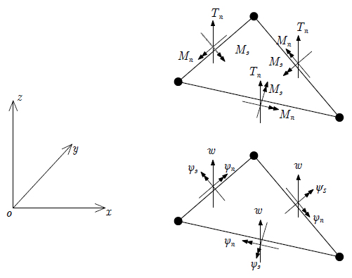
As shown in Figure 1, the positive directions of displacement components and resultants are defined. The xoy-plane represents the middle surface of Mindlin plate, and the z-axis represents the direction of thickness (the thickness is denoted by h).
In the mid-surface of Mindlin plate, the transverse deflection along z-axis is denoted by w, and the rotations of normal vector in xoz-plane and yoz-plane are denoted by ψx andψy , respectively. Obviously, the deflection w, the rotation ψx , and the rotation ψy are all functions of x and y. And the displacement components at arbitrary point in the plate are given by equation (1).
As the deflection and rotations are independently defined, the rotations ψx and ψy are no more equal to the rotations of mid-surface. The transverse shear strain vector is determined by the difference of the two aforementioned kinds of rotations.
From the displacements given in equation (1), the strains paralleled with the xoy-plane at arbitrary point in Mindlin plate can be obtained:
where κ is the curvature vector. And from equations (2) and (3), the strain compatibility equations can be derived:
The bending moments, twisting moment, and shear forces are denoted by Mx , My , Mxy , Tx , and Ty , respectively, as shown in Figure 1. And the equilibrium equations for a plate under transverse distributed load q are:
As shown in Figure 2, Mn , Ms , and Tn denote the bending moment, twisting moment, and shear force along boundary, respectively; ψn , ψs , and w denote the boundary rotations and deflection, respectively.
The relations between the domain and the boundary resultants, as well as the relations between the domain and the boundary displacement components, are given by
where l and m are the direction cosines of the boundary’s outer normal.
The constitutive equations for isotropic and linearly elastic Mindlin-Reissner plates with uniform thickness are:
where M, T, D b , and D s are the bending moment vector, shear force vector, bending elasticity matrix, and shear elasticity matrix, respectively;
in which E, G, and μ are the Young’s modulus, shear modulus, and Poisson’s ratio, respectively; and h is the thickness of the plate.
Generally, the boundary conditions (BCs) are classified into four categories: 1) Fixed boundary (S 1) condition: deflection and rotations of the boundary are given; 2) ‘Soft’ simply supported (SS 1) condition: deflection, bending moment and twisting moment of the boundary are given; 3) ‘Hard’ simply supported (SS 2) condition: deflection, bending moment and rotation ψs of the boundary are given; and 4) Free boundary (S 3) condition: all the boundary resultants are given.
2.2 The Modified Principle of Complementary Energy for Mindlin-Reissner Plate
The standard complementary energy functional for Mindlin-Reissner plate is given below (Hu, 1984Hu, H.C. (1984). Variational Principle of Theory of Elasticity with Applications, Science press, Beijing.):
in which Su ; Ω denotes the whole mid-surface region of the plate; C and R denote the elasticity matrix of compliances and the resultant vector, respectively; ,
,  , and
, and  denote the given boundary displacement components on the displacement boundary
Assume that the region Ω is divided into several subregions (triangles) Te (e=1 ˜ N). And the given trial functions of resultants satisfy the equilibrium equations in each subregionTe . In order to make use of the principle of minimum complementary energy, extra constrains should be imposed. According to the generalized variational principle, such extra constrains can be imposed by the so-called Lagrange multiplier method.
Extra constrains include the equilibrium conditions on the common boundaries of subregions and the force boundary conditions on the boundary of Ω, which are expressed by:
where ΣSe denotes the common boundaries of subregions; the indexes 1 and 2 denote the two subregions that share a common boundary;
where Sσ denotes the force boundary;  , and
, and  represent the given boundary resultants.
 ,
,
By multiplying the two constrains by corresponding Lagrange multipliers and adding them into the standard complementary energy functional (equation (12)), the modified functional can be obtained:
where λ 1 and λ 2 are Lagrange multipliers.
Let the variation of equation (17) be zero:
Here the relations (6) between domain and boundary resultants have been already considered.
Considering the following constitutive equation:
where F is an operator matrix, the area integral in equation (18) can be simplified. Integrate by parts for the area integral, we obtain
in which F; n is the corresponding direction matrix; and ∂Te denotes the boundary of the e-th subregion; is the adjoint operator of
where l and m are still the direction cosines of boundary’s outer normal.
Because the trial functions of resultants satisfy the equilibrium equations in each subregion, variation of equations (5) yields following result:
Thus, equation (18) can be simplified as
In above equation, only curvilinear integral exists. From equation (7), and using the relation
equation (23) can be further simplified to be
Due to the arbitrariness of variation about resultants δ R, it can be easily concluded that the Lagrange multipliers are just (boundary) displacement components on corresponding boundaries. Finally, the modified functional of complementary energy can be fully determined:
2.3 The Displacement Function of Mindlin-Reissner Plate
Hu (1984Hu, H.C. (1984). Variational Principle of Theory of Elasticity with Applications, Science press, Beijing.) proposed the so-called displacement functions F and f for Mindlin-Reissner plates, from which the displacement components can be derived theoretically.
For a plate loaded by distributed transverse force q, the displacement components are given as
where D and C are bending stiffness and shear stiffness mentioned in equation (11), respectively. The functions F and f satisfy the following differential equations.
It should be noted that equation (27) is quite similar to the governing equation of the deflection for thin plates under Kirchhoff’s assumption. In fact, Hu pointed out that function F even satisfies the same boundary conditions as the deflection of thin plates if the plate is thin enough. Function f represents the influence of shear deformation, and describes the phenomenon of edge effect for Mindlin plates. In some cases, the function f vanishes, such as simply supported polygonal plates, circular plates of axial symmetry and other cases in which the shear forces are statically determinate (Hu, 1984Hu, H.C. (1984). Variational Principle of Theory of Elasticity with Applications, Science press, Beijing.). In this paper, only F is considered, because the influence region of f is near the boundary, and the contribution of f to the total energy and the displacement solutions is insignificant. Actually, in higher-order elements, the influence of displacement function f must be taken into account, otherwise the elements may present poor results for stress and strain, even for nodes away from the boundary (Bao et al., 2017Bao, Y., Cen, S., Li, C.F. (2017). Distortion-resistant and locking-free eight-node elements effectively capturing the edge effects of Mindlin-Reissner plates. Engineering Computations 34(2): in press.).
Substitution of equation (26) into equations (2) and (3) yields
Then, substitution of equation (29) into the constitutive equations (8) yields
It is emphasized that the curvatures, shear strains, and resultants derived from displacement function F satisfy all governing equations of Mindlin-Reissner plates. Thus, it’s quite reasonable to gain proper trial functions by means of displacement functions.
Assumed that the distributed transverse force q is constant, then, the displacement function F can be solved.
in which F is expressed as the sum of the general and the particular solutions.
Considering the symmetry between x and y axes, the particular solution can be chosen as (other choices such as F * = q / 8D x 2 y 2 have been also tested, but the following one is better.)
And the general solutions of F satisfy the following governing equation,
which can be easily solved in polynomial form. The first seven general solutions and corresponding resultants are listed in Table 1. The first order completeness of bending moments and zero order completeness of shear forces are guaranteed. More analytical solutions can be found in reference (Cen et al., 2014Cen, S., Shang, Y., Li, C.F., Li, H.G. (2014). Hybrid displacement function element method: a simple hybrid-Trefftz stress element method for analysis of Mindlin-Reissner plate. International Journal for Numerical Methods in engineering 98(3):203-234.).
2.4 The Locking-free Formulae of Timoshenko’s Beam
As shown in Figure 3, in locking-free formulae of Timoshenko’s beam (Hu, 1984Hu, H.C. (1984). Variational Principle of Theory of Elasticity with Applications, Science press, Beijing.), the deflection w, rotation ψ, and shear strain γ are assumed to be cubic, quadratic, and constant, respectively, and are given by
in which
Here D and C represent the beam’s bending stiffness and shear stiffness, respectively, and will be replaced by corresponding stiffness of Mindlin plates in the following section.
As discussed in Section 1, the interpolation technique based on the formulae of Timoshenko’s beam has been successfully applied in many effective elements (Soh et al., 1999Soh, A.K., Long, Z.F., Cen, S. (1999). A new nine DOF triangular element for analysis of thick and thin plates. Computational Mechanics 24(5):408-417.).
3 FORMULAE OF THE NEW ELEMENT HDF-P3-7Β
Figure 4 shows a 9-DOF triangular plate bending element, and assume that the whole plate Ω is meshed into several triangles Te (e=1˜N).
Firstly, the assumed resultant fields can be derived from the aforementioned solutions of displacement function F:
in which R 0 denotes the general solution part, and is taken as a linear combination of the first seven general solutions of F listed in Table 1:
where βi (i=1˜7) are unknown resultant parameters, and R i (i=1˜7) are the resultant vectors derived from the first seven general solutions of F by employing equation (30), which have been given by Table 1; R * denotes the particular solution part, and can be derived directly from the particular solution of F and equation (30):
Thus, the assumed resultants satisfy the equilibrium equations in each subregionTe . So, the modified functional of complementary energy given in Section 2 can be employed.
Secondly, the displacement components along each element boundary are chosen as the locking-free formulae of Timoshenko’s beam theory.
Substitution of the relations
into equation (34) yields
Then, the rotation along normal direction is assumed to be linear function.
These three complicated equations can be rewritten in the form of matrix:
where q
e is the nodal displacement vector of the e-th element, and  is the boundary displacement interpolation function matrix or shape function matrix.
It is easy to see that the matrices  on different edges are different:
All the non-zero components can be detailed directly from equations (40) and (41).
Thirdly, as the assumed resultants and boundary displacement components are all given, the modified functional of complementary energy can be fully determined.
Let
then, the modified functional of complementary energy can be simplified as:
in which β e denotes the resultant parameter vector of the e-th element. It should be emphasized that the resultant parameter vectors of different elements are independently defined, so that they can vary independently.
Using the modified principle of complementary energy, the variation of modified functional (45) is taken to be zero:
in which q is the global nodal displacement vector of the plate. And above variational equations yield
which gives the relation between β e and q e . It may be found that equation (48) is not so rigorous, and some assembling rules should be discussed.
Equation (47) yields
Substitution of equation (49) into equation (48) yields
Above equation gives the discrete global equilibrium equation for this kind of element:
in which the summation notation means that some assembling rules of element equilibrium equations should be followed. In fact, the assembling rule is the same as what we use in traditional displacement-based element cases, which can be easily found from equation (50).
It should be noted that:
The element stiffness matrix is just H T M -1 H;
Now it can be explained that why only the first seven general solutions of resultants are employed. To avoid spurious zero energy modes, the rank of single element stiffness matrix should be at least 9−3=6, which means that at least six general solutions should be included. Completeness requirement tells us that seven solutions or eleven solutions are reasonable choices, but numerical results show that seven solutions are enough and always achieve higher accuracy.
2) The element equivalent nodal force vector is also given in equation (51);
In above equation, (V T - H T M -1 M *) denotes the equivalent nodal forces of body forces, and the last part denotes the equivalent forces of boundary forces.
Then, the element equilibrium equation can be written as P e - K e q e = 0, and equation (51) is the assembled global equilibrium equation. It is surprising but reasonable that the equivalent forces of boundary forces possess the same form as displacement-based elements.
3) The assembling rules of hybrid displacement function elements are consistent with traditional displacement-based elements. So it can be easily integrated into the standard framework of finite element programs.
The integrals in equation (44) are all calculated by numerical integration methods. One dimensional Gauss integration and Hammer integration schemes are employed. As the integrands are polynomials, all the integrals can be calculated exactly. In this paper, four integration points are employed for both line integrals and area integrals in equation (44), and it can be sure that the results are all accurate.
Following the aforementioned steps, the global nodal displacement components can be solved. Then, substitute the known element displacement vector q e into
the resultants at arbitrary point of the element can be obtained. Furthermore, the resultants at any nodes can be taken as the average value of different elements.
Once the stiffness matrix for static analysis is derived, what we need to extend the proposed element into free vibration analysis of Mindlin plate is the formulae of inertia matrix. Considering the corresponding variational principles for free vibration problems, hybrid element method can be extended into the analysis of free vibration problems theoretically. But as we mentioned in Section 1, such scheme does not give the formulae of inertia matrix and a nonlinear eigenvalue problem has to be solved.
Actually, some inertia matrices of displacement-based elements can cooperate well with the stiffness matrix of the proposed element in analyzing the free vibration of plate structures. And the diagonal inertia matrix of the 3-node triangular isoparametric element is almost the best choice, for both convergence property and computational cost. Thus, though no rigorous mathematical proof has been given yet, the generalized eigenvalue equation is still given by
where 𝒬 is the density of the plate, A is the area of the e-th element and ω is the natural frequency. Since the stiffness matrix and inertia matrix are symmetric, this eigenvalue problem can be solved by the subspace iteration method (Bathe and Wilson, 1973Bathe, K.J. and Wilson, E.L. (1973). Solution methods for eigenvalues problems in Structural Mechanics. International Journal for Numerical Methods in Engineering 6(2):213-226.), and the frontal method is also employed in computer coding for saving computer memory (Liu, 1989Liu, G. (1989). A method for large scale finite element dynamic analysis. Chinese Journal of Computational Mechanics 6(1):247-251 (in Chinese).).
4 NUMERICAL EXAMPLES
Several standard numerical examples are employed in this section to test the performance of the proposed element HDF-P3-7β. And results obtained by following models are also given for comparison.
DKT: Triangular discrete Kirchhoff element proposed by Batoz et al. (1980Batoz, J.L., Bathe, K.J., Ho, L.W. (1980). A study of three-node triangular plate bending elements. International Journal for Numerical Methods in Engineering 15(12):1771-1812.).
DKTM, RDKTM: Refined triangular Mindlin plate elements proposed by Chen et al. (2001Chen, W.J. and Cheung, Y.K. (2001). Refined 9-Dof triangular Mindlin plate elements. International Journal for Numerical Methods in Engineering 51(11):1259-1281.).
DST-BL: A compatible triangular Mindlin plate element based on the discrete shear triangle technique proposed by Batoz et al. (1989Batoz, J.L. and Lardeur, P. (1989). A disrete shear triangular nine dof element for the analysis of thick to very thin plates. International Journal for Numerical Methods in Engineering 28(3):533-560.).
DST-BK: An incompatible triangular Mindlin plate element based on the discrete shear triangle technique proposed by Batoz et al. (1992Batoz, J.L. and Kaliti, I. (1992). On a simple triangular Reissner/Mindlin plate element based on incompatible modes and discrete constrains. International Journal for Numerical Methods in Engineering 35(8):1603-1632.).
MITC4: A quadrilateral Mindlin-Reissner plate element based on a mixed interpolation scheme proposed by Bathe et al. (1985Bathe, K.J. and Dvorkin, E.N. (1985). A four-node plate bending element based on Mindlin-Reissner plate theory and a mixed interpolation. International Journal for Numerical Methods in Engineering 21(2):367-383.).
THS: A triangular hybrid stress element based on analytical solutions of thin plate equations proposed by Rezaiee-Pajand et al. (2014Rezaiee-Pajand, M. and Karbon, M. (2014). Hybrid stress and analytical functions for analysis of thin plate bending. Latin American Journal of Solids and Structures 11(4):556-579.).
ARS-T9: A triangular Mindlin plate element based on the improved shear strain interpolation derived from the locking-free Timoshenko’s beam element proposed by Soh et al. (1999Soh, A.K., Long, Z.F., Cen, S. (1999). A new nine DOF triangular element for analysis of thick and thin plates. Computational Mechanics 24(5):408-417.).
T3BL, T3BL(R): Triangular Mindlin plate elements based on the linked interpolation method proposed by Taylor and Auricchio (1993Taylor, R.L. and Auricchio, F. (1993). Linked interpolation for Reissner-Mindlin plate elements: Part II-a simple triangle. International Journal for Numerical Methods in Engineering 36(18):3057-3066.).
MiSP3: Hybrid-mixed Mindlin plate elements based on the mixed shear projected method proposed by Ayad et al. (1998Ayad, R., Dhatt, G., Batoz, J.L. (1998). A new hybrid-mixed variational approach for Reissner-Mindlin plates. The MiSP model. International Journal for Numerical Methods in Engineering 42(7):1149-1179.).
MiSP3+: An improved triangular hybrid-mixed Mindlin plate element proposed by Ayad et al. (2001Ayad, R., Rigolot, A., Talbi, N. (2001). An improved three-node hybrid-mixed element for Mindlin/Reissner plates. International Journal for Numerical Methods in Engineering 51(8):919-942.).
NS+ES-FEM: A ‘hybrid’ smoothed element proposed by Wu et al. (2014Wu, F., Liu, G.R., Cheng, A.G., He, Z.C. (2014). A new hybrid smoothed FEM for static and free vibration analyses of Reissner-Mindlin plates. Computational Mechanics 54(3):865-890.).
MIN3: A 3-node Mindlin plate element with improved transverse shear proposed by Tessler et al. (1985Tessler, A. and Hughes, T.J.R. (1985). A three-node Mindlin plate element with improved transverse shear. Computer Methods in Applied Mechanics and Engineering 50(1):71-101.).
DSG3: Mindlin plate element based on the discrete shear gap method proposed by Bletzinger et al. (2000Bletzinger, K.U., Bischoff, M., Ramm, E. (2000). A unified approach for shear-locking-free triangular and rectangular shell finite elements. Computer & Structure 75(3):321-334.).
NS-DSG3, ES-DSG3: Two smoothed Mindlin plate elements of the smoothed FEM family proposed by Liu et al. (2009aLiu, G.R., Nguyen-Thoi, T., Nguyen-Xuan, H., Lam, K.Y. (2009a). A node-based smoothed finite element (NS-FEM) for upper bound solutions to solid mechanics problems. Computer & Structures 87(1-2):14-26., 2009bLiu, G.R., Nguyen-Thoi, T., Lam, K.Y. (2009b). An edge-based smoothed finite element method (ES-FEM) for static, free and forced vibration analyses of solids. Journal of Sound and Vibration 320(4-5):1100-1130.).
S4R, S3R: The quadrilateral and triangular shell elements assembled in the renowned commercial FEM software Abaqus (2009Dassault Systèmes Simulia Corp., (2009). Abaqus 6.9 HTML Documentation, Providence, RI.).
4.1 Numerical Examples: Static Analyses
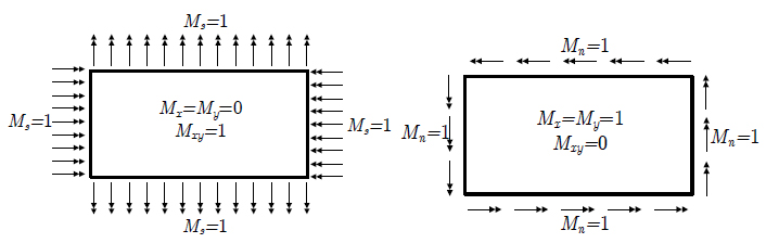
4.1.1 Patch Tests
As shown in Figure 5, a patch is divided by four elements. Three kinds of thickness are considered. Proper constrains are imposed to eliminate rigid body motions. The size and constants are also given in the figure. Both pure bending boundary forces and pure twisting boundary forces are tested, and these two cases are shown in Figure 6.
Numerical results in Table 2 show that the patch tests are perfectly passed for both thin and moderately thick plates, so that the convergence should be guaranteed. In fact, as these two constant moment cases are all included in the first seven general solutions of resultants, which are the trial functions for the resultant fields, it is reasonable that exact solutions can be obtained.
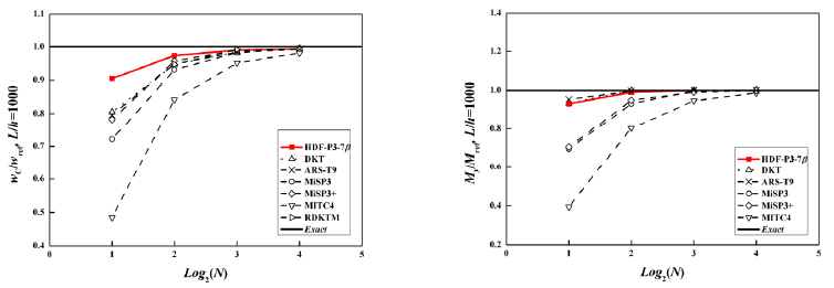
4.1.2 Square Plate Loaded by Uniform Distributed Transverse Load
As shown in Figure 7, due to the symmetry, only a quarter of plate is calculated. Clamped boundary condition and hard simply supported boundary condition are considered. The span, distributed transverse force, bending stiffness, Poisson’s ratio, and thickness of the plate are denoted by L, q, D, μ, and h, respectively, and are given by
L=1, q=1, D=1, μ=0.3, h=0.001, 0.1.
The deflection and bending moment at the plate center
calculated by the proposed element, which are compared with the reference solutions (Taylor and Auricchio, 1993Taylor, R.L. and Auricchio, F. (1993). Linked interpolation for Reissner-Mindlin plate elements: Part II-a simple triangle. International Journal for Numerical Methods in Engineering 36(18):3057-3066.), are listed in Table 3. Comparisons with results obtained by other elements are plotted in Figure 8 and Figure 9. From these results, it can be concluded that the proposed HDF-P3-7β element shows better convergence in most of square plate cases.
Hard simply supported boundary case: the plate central deflection and bending moment results.
4.1.3 Skew Plates Loaded by Uniform Distributed Transverse Load
Razzaque’s 60° plate
As shown in Figure 10, a 60° skew plate with two free and two soft simply supported edges was firstly used by Razzaque (1973Razzaque, A. (1973). Program for triangular bending elements with derivative smoothing. International Journal for Numerical Methods in Engineering 6(3):333-343.) to test the accuracy of thin plate elements, and it has been treated as a classical benchmark for both thin and thick plate elements. The edge length, transverse force, thickness, Young’ modulus, and Poisson’s ratio are denoted by L, q, h, E, and μ, respectively, and are given by
L=100, q=1, h=0.1, E=10.92, μ=0.3.
For the central deflection w C and bending moment My at point C, Razzaque (1973Razzaque, A. (1973). Program for triangular bending elements with derivative smoothing. International Journal for Numerical Methods in Engineering 6(3):333-343.) give out the finite difference solutions:
Results obtained by different elements are listed in Table 4 and plotted partly in Figure 11. It can be easily concluded that the proposed element gives almost the best solutions for both deflection and bending moment.
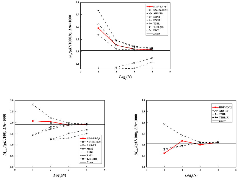
Morley’s 30° plate
As shown in Figure 12, a 30° plate with four soft simply supported edges is considered. It’s a more singular problem than the previous one. The earliest solution is calculated based on Kirchhoff theory by Morley (1963Morley, L.S.D. (1963). Skew Plates and Structures, Macmillan, New York.).
The edge length, thickness, Young’s modulus, and Poisson’s ratio are denoted by L, h, E, and μ, respectively, and are given by
L=100, h=0.1, E=10.92, μ=0.3.
Then, the central deflection, maximum, and minimum bending moments at point O are evaluated. Morley’s results are employed as the reference solutions.
Results of central deflection and two principal bending moments are listed in Table 5, and plotted in Figure 13.
It can be seen that good convergence is achieved nearly by all the elements, but the proposed element provides higher accuracy for bending moments.
4.1.4 Circular Plate Under Uniform Distributed Transverse Load
Similar to the square plate problem, a quarter of circular plate is investigated and symmetric boundary conditions are imposed on corresponding edges, as shown in Figure 14.
Soft simply supported (SS 1) boundary condition is applied to the plates. For this axial symmetric problem, analytical solutions can be derived from the Mindlin-Reissner plate theory (Batoz and Dhatt, 1990Batoz, J.L. and Dhatt, G. (1990). Modèlisation des Structures par Eléments Finis, Vol. 2: Poutres et Plaques, Editions Hermès, Paris.). The radius, uniform distributed transverse load, thickness, Young’s modulus, and Poisson’s ratio are denoted by R, q, h, E, and μ, respectively.
The central deflection and bending moment of soft simply supported circular plates are given as
Related parameters are set to be
R=5, h=0.1, 1, E=10.92, μ=0.3.
The normalized results of the deflection and the bending moment at plate center are given in Table 6. And corresponding data are also plotted in Figure 15.
Furthermore, the shear force and bending moments along the radius of both thin (R/h=50) and thick (R/h=5) clamped plate are also compared with the analytical solutions (Batoz and Dhatt, 1990Batoz, J.L. and Dhatt, G. (1990). Modèlisation des Structures par Eléments Finis, Vol. 2: Poutres et Plaques, Editions Hermès, Paris.). These numerical results are calculated by 96 proposed elements. And all data are listed in Table 7 and plotted in Figure 16. The analytical solutions are given as
From the resultant force solutions for clamped circular plate, the following deflection equation can be obtained:
Then, the strain energy of a quarter of plate can be calculated by employing the virtual work principle, that is to say, the strain energy is equal to a half of the work of the distributed load.
In present model, the strain energy (the same as complementary energy for linear elastic material) is evaluated via the resultant force results given by equation (54):
where the index h denotes numerical solutions.
Thus, the energy error will be calculated by (U−Uh )/U, and the energy norm error is the square root of (U−Uh )/U. Following these notations, the energy norm error results can be obtained and are listed in Table 8. It can be simply concluded that the convergence rate is about 1 for both thin and moderately thick plates.
High accuracy is achieved by the proposed element HDF-P3-7β for both central deflection and bending moment of the circular plate. And it is of particular interest that the resultants along the radius coincide perfectly with the analytical solutions.
4.1.5 Rotational Frame Dependence Test
In order to show that there is no rotational frame dependence, 30° and 60° skew plates are tested with the global frame rotated. Central deflection of the plate is calculated using 2×8×8 elements with the frame rotated counterclockwise in steps of 15°. Parameters of these plates are almost the same as the aforementioned ones. Taking the distributed load to be 1, deflection results are listed in Table 9.
With the numerical error considered, it can be concluded from the above table that the solutions calculated by HDF-P3-7β are independent of the global frame rotation, which is because that corresponding completeness of resultants is guaranteed.
4.2 Numerical Examples: Free Vibration Analyses
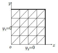
4.2.1 Free Vibration of Square Plates
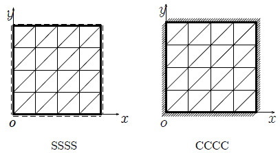
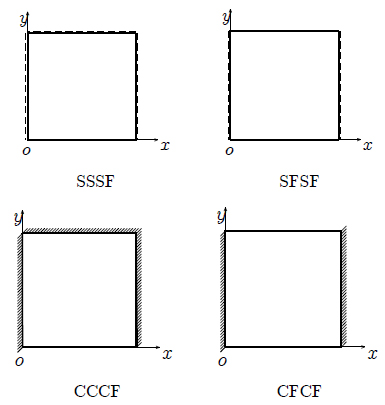
As shown in Figure 17, two plates with four hard simply supported (SSSS) edges and four fixed (CCCC) edges are calculated to evaluate the performance of the proposed element. The span, thickness, density, Young’s modulus, and Poisson’s ratio of the plate are denoted by L, h, ρ, E, and μ, respectively, and are given by
L=10, h=0.05, 1, 𝒬=8000, E=2×10¹¹, μ=0.3.
Both thin (h=0.05) and moderately thick (h=1) plates are studied and the non-dimensional frequencies are calculated by
where D is the aforementioned bending stiffness of Mindlin plate given in equation (11).
For the SSSS thin square plate, the free vibration frequencies can be derived theoretically and given by the following equation (Leissa, 1969Leissa, A.W. (1969). Vibration of plates, OHIO STATE UNIV COLUMBUS.).
where m and n are natural numbers.
The reference solutions for CCCC thin plates are proposed by Young (1950Young, D. (1950). Vibration of rectangular plates by the Ritz method. Journal of Applied Mechanics-Transactions of the ASME 17(4):448-453.). And in other cases, the reference solutions can be found in the book of Abassian et al. (1987Abassian, F., Hawswell, D.J., Knowles, N.C. (1987). Free vibration benchmarks, Glasgow: Department of Trade and Industry, National Engineering Laboratory.).
Normalization of the five lowest non-dimensional frequencies are listed in Table 10, Table 11, Table 12 and Table 13, where those results of some other elements are also given for comparison. The results of various elements using a mesh of 8×8×2 elements are plotted in Figure 18 and Figure 19.
Normalized non-dimensional frequency parameters for square plates with SSSS BCs (L/h=200).
Normalized non-dimensional frequency parameters for square plates with CCCC BCs (L/h=200).
Thin square plates (h=0.05) with various boundary conditions (as shown in Figure 20) are also analyzed by the proposed element using a 16×16 mesh. These problems are more challenging and two sets of reference solutions are considered, first of which is calculated by 500×500 S4R elements in the commercial FEM software Abaqus (2009), while the second is suggested by Leissa (1969Leissa, A.W. (1969). Vibration of plates, OHIO STATE UNIV COLUMBUS.). The non-dimensional frequencies are given by
Normalized results of the lowest four non-dimensional frequencies (normalized by the first set of reference frequencies) are listed in Table 14 and compared with the results obtained by some other elements.
Normalized non-dimensional frequency parameters for square plates with various BCs (L/h=200).
As shown in above numerical examples, the free frequencies of square plates obtained by the proposed element exhibit higher precision over other elements. And ideal solutions can be obtained by element HDF-P3-7β for relatively higher order frequencies with only coarse meshes.
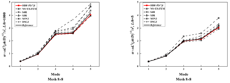
4.2.2 Free Vibration of Parallelogram Plates
As shown in Figure 21, a cantilevered 60° parallelogram plate with a fixed edge and three free edges is investigated. The density, Young’s modulus, and Poisson’s ratio are the same as those in previous square plate example, and two kinds of thickness-span ratio, thin and moderately thick cases, are considered:
L=100, h=0.1, 20.
The non-dimensional frequencies are calculated by the following equation:
Compared with the reference solutions given by Karunasena et al. (1996Karunasena, W., Liew, K.M., Al-Bermani, F.G.A. (1996). Natural frequencies of thick arbitrary quadrilateral plates using the pb-2 Ritz method. Journal of Sound and Vibration 196(4):371-385.) using pb-2 Ritz method, as presented in Table 15 and Table 16, better performance can be produced by the proposed element than other elements like S4R, DSG3 and MIN3. And the proposed element HDF-P3-7β possesses nearly the same (even better) accuracy as NS+ES-FEM. A direct comparison is plotted in Figure 22.
Normalized non-dimensional frequency parameters for cantilevered parallelogram plates (L/h=1000).
Normalized non-dimensional frequency parameters for cantilevered parallelogram plates (L/h=5).
4.2.3 Free Vibration of Circular Plates
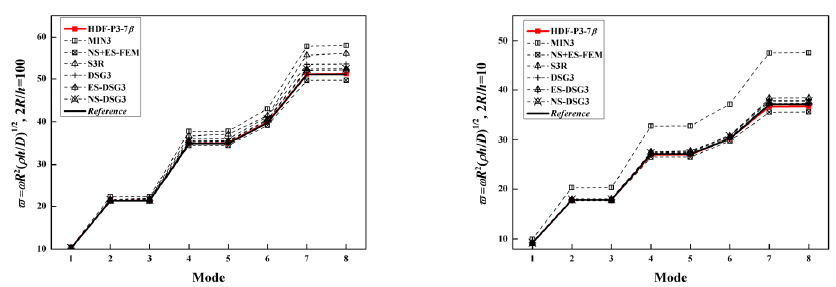
The lowest eight frequencies of clamped circular plates with the mesh shown in Figure 23 are investigated. 393 proposed elements and 221 nodes are used to discretize the whole plate, while the compared solutions given by other elements employ even finer meshes. The frequencies given by S3R use the same mesh as the proposed element, but the solutions of MIN3 and NS+ES-FEM employ a mesh of 394 elements and 222 nodes, and the solutions of DSG3, NS-DSG3 and ES-DSG3 employ a much finer mesh of 848 elements and 460 nodes.
The material property parameters are remained unchanged, and the radius and thickness of the circular plates are:
R=5, h=0.1, 1.
Non-dimensional parameters of the frequencies are computed by the following equation:
Reference solutions of this benchmark are suggested by Leissa (1969Leissa, A.W. (1969). Vibration of plates, OHIO STATE UNIV COLUMBUS.) (for the thin plate) and Irie et al. (1980Irie, T., Yamada, G., Aomura, S. (1980). Natural frequencies of Mindlin circular plates. Journal of Applied Mechanics 47(3):652-655.) (for the thick case).
It is noticeable that the proposed element produces the most accurate solutions while employing the coarsest mesh, which owes to the analytical trial function method used to formulate the element. And the solutions given by different elements are listed in Table 17 and Table 18 and plotted in Figure 24, from which a visualized comparison may be obtained.
Normalized non-dimensional frequency parameters for circular plates with clamped BCs (2R/h=100).
Normalized non-dimensional frequency parameters for circular plates with clamped BCs (2R/h=10).
5 CONCLUSION
A new triangular hybrid displacement function element is formulated and evaluated in this paper. This element is based on the modified principle of complementary energy and the so-called displacement function. With the locking-free formulae of Timoshenko’s beam employed and the assumed resultants satisfying all governing equations, the proposed element HDF-P3-7β achieves high accuracy for both displacement components and resultants, and it is totally locking-free, which is because that it’s a stress-based element and the thin plate solutions are included in the selected resultant fields. Cooperating with the inertia matrix of 3-node triangular isoparametric element, the proposed element can be successfully applied in free vibration problems and give precise solutions for vibration frequency. This element can be also integrated into the standard framework of finite element program conveniently.
This hybrid displacement function element method was firstly introduced by Cen et al. (2014Cen, S., Shang, Y., Li, C.F., Li, H.G. (2014). Hybrid displacement function element method: a simple hybrid-Trefftz stress element method for analysis of Mindlin-Reissner plate. International Journal for Numerical Methods in engineering 98(3):203-234.). In this paper, a more rigorous but complicated description of the hybrid displacement function element method from the viewpoint of the principles in mechanics is given, which gives the formulae of the equivalent nodal forces directly.
Numerical examples show that the proposed element performs well, especially for the resultants and free vibration frequencies. For the circular plate problem, resultants along the radius coincide perfectly with the corresponding analytical solutions, which is hardly satisfied by many classical displacement-based Mindlin plate elements. Last but not least, this element is independent of the frame rotation, which is because that corresponding completeness of resultants is guaranteed.
Although the patch tests are passed, the convergence may not be guaranteed using existed theory, because the proposed element is not displacement-based. A following work is the rigorous proof for the convergence of the hybrid displacement function element method, and is still being studied. Since the employment of the inertia matrices of displacement-based element has not been studied before, it’s also of remarkable importance.
Acknowledgments
The authors would like to acknowledge the financial supports of the National Natural Science Foundation of China (Project No. 11272181), the Specialized Research Fund for the Doctoral Program of Higher Education of China (Project No. 20120002110080), and the Tsinghua University Initiative Scientific Research Program (Project No. 2014z09099).
References
- Abassian, F., Hawswell, D.J., Knowles, N.C. (1987). Free vibration benchmarks, Glasgow: Department of Trade and Industry, National Engineering Laboratory.
- Ayad, R., Dhatt, G., Batoz, J.L. (1998). A new hybrid-mixed variational approach for Reissner-Mindlin plates. The MiSP model. International Journal for Numerical Methods in Engineering 42(7):1149-1179.
- Ayad, R., Rigolot, A., Talbi, N. (2001). An improved three-node hybrid-mixed element for Mindlin/Reissner plates. International Journal for Numerical Methods in Engineering 51(8):919-942.
- Bao, Y., Cen, S., Li, C.F. (2017). Distortion-resistant and locking-free eight-node elements effectively capturing the edge effects of Mindlin-Reissner plates. Engineering Computations 34(2): in press.
- Bathe, K.J. and Dvorkin, E.N. (1985). A four-node plate bending element based on Mindlin-Reissner plate theory and a mixed interpolation. International Journal for Numerical Methods in Engineering 21(2):367-383.
- Bathe, K.J. and Wilson, E.L. (1973). Solution methods for eigenvalues problems in Structural Mechanics. International Journal for Numerical Methods in Engineering 6(2):213-226.
- Bathe, K.J., Cho, S.W., Buchalem, M.L., Brezzi, F. On our MITC plate bending/shell elements, in: Analytical and Computational Models for shells, Noor A.K. et al., Eds., (1989) CED 3:261-278, ASME Special Publication.
- Batoz, J.L. and Dhatt, G. (1990). Modèlisation des Structures par Eléments Finis, Vol. 2: Poutres et Plaques, Editions Hermès, Paris.
- Batoz, J.L. and Kaliti, I. (1992). On a simple triangular Reissner/Mindlin plate element based on incompatible modes and discrete constrains. International Journal for Numerical Methods in Engineering 35(8):1603-1632.
- Batoz, J.L. and Lardeur, P. (1989). A disrete shear triangular nine dof element for the analysis of thick to very thin plates. International Journal for Numerical Methods in Engineering 28(3):533-560.
- Batoz, J.L., Bathe, K.J., Ho, L.W. (1980). A study of three-node triangular plate bending elements. International Journal for Numerical Methods in Engineering 15(12):1771-1812.
- Belytschko, T. and Bachrach, W.E. (1986). Efficient implementation of quadrilaterals with high coarse-mesh accuracy. Computer Methods in Applied Mechanics and Engineering 54(3):279-301.
- Bletzinger, K.U., Bischoff, M., Ramm, E. (2000). A unified approach for shear-locking-free triangular and rectangular shell finite elements. Computer & Structure 75(3):321-334.
- Cen, S. and Shang, Y. (2015). Developments of Mindlin-Reissner plate elements. Mathematical Problems in Engineering 2015:1-12.
- Cen, S., Shang, Y., Li, C.F., Li, H.G. (2014). Hybrid displacement function element method: a simple hybrid-Trefftz stress element method for analysis of Mindlin-Reissner plate. International Journal for Numerical Methods in engineering 98(3):203-234.
- Chen, W.J. and Cheung, Y.K. (2001). Refined 9-Dof triangular Mindlin plate elements. International Journal for Numerical Methods in Engineering 51(11):1259-1281.
- Dassault Systèmes Simulia Corp., (2009). Abaqus 6.9 HTML Documentation, Providence, RI.
- Hu, H.C. (1984). Variational Principle of Theory of Elasticity with Applications, Science press, Beijing.
- Hughes, T.J.R. and Tezduyar, T.E. (1981). Finite elements based upon Mindlin plate theory with particular reference to the four-node bilinear isoparametric element. Journal of Applied Mechanics 48(3):587-596.
- Hughes, T.J.R., Taylor, R.L., Kanoknukulchai, W. (1977). A simple and efficient finite element for plate bending. International Journal for Numerical Methods in Engineering 11(10):1529-1543.
- Irie, T., Yamada, G., Aomura, S. (1980). Natural frequencies of Mindlin circular plates. Journal of Applied Mechanics 47(3):652-655.
- Karunasena, W., Liew, K.M., Al-Bermani, F.G.A. (1996). Natural frequencies of thick arbitrary quadrilateral plates using the pb-2 Ritz method. Journal of Sound and Vibration 196(4):371-385.
- Katili, I. (1993). A new discrete Kirchhoff-Mindlin element based on Mindlin-Reissner plate theory and assumed strain fields-Part I: an extended DKT element for thick-plate bending analysis. International Journal for Numerical Methods in Engineering 36(11):1859-1883.
- Leissa, A.W. (1969). Vibration of plates, OHIO STATE UNIV COLUMBUS.
- Liu, G. (1989). A method for large scale finite element dynamic analysis. Chinese Journal of Computational Mechanics 6(1):247-251 (in Chinese).
- Liu, G.R., Nguyen-Thoi, T., Lam, K.Y. (2009b). An edge-based smoothed finite element method (ES-FEM) for static, free and forced vibration analyses of solids. Journal of Sound and Vibration 320(4-5):1100-1130.
- Liu, G.R., Nguyen-Thoi, T., Nguyen-Xuan, H., Lam, K.Y. (2009a). A node-based smoothed finite element (NS-FEM) for upper bound solutions to solid mechanics problems. Computer & Structures 87(1-2):14-26.
- Morley, L.S.D. (1963). Skew Plates and Structures, Macmillan, New York.
- Nguyen-Xuan, H., Rabczuk, T., Bordas, S., Debongnie, J.F. (2008). A smoothed finite element method for plate analysis. Computer Methods in Applied Mechanics and Engineering 197(13-16):1184-1203.
- Razzaque, A. (1973). Program for triangular bending elements with derivative smoothing. International Journal for Numerical Methods in Engineering 6(3):333-343.
- Rezaiee-Pajand, M. and Karbon, M. (2014). Hybrid stress and analytical functions for analysis of thin plate bending. Latin American Journal of Solids and Structures 11(4):556-579.
- Soh, A.K., Long, Z.F., Cen, S. (1999). A new nine DOF triangular element for analysis of thick and thin plates. Computational Mechanics 24(5):408-417.
- Tabarrok, B. (1971). A variational principle for the dynamic analysis of continua by hybrid element method. International Journal of Solids and Structures 7(3):251-268.
- Taylor, R.L. and Auricchio, F. (1993). Linked interpolation for Reissner-Mindlin plate elements: Part II-a simple triangle. International Journal for Numerical Methods in Engineering 36(18):3057-3066.
- Tessler, A. and Hughes, T.J.R. (1985). A three-node Mindlin plate element with improved transverse shear. Computer Methods in Applied Mechanics and Engineering 50(1):71-101.
- Wu, F., Liu, G.R., Cheng, A.G., He, Z.C. (2014). A new hybrid smoothed FEM for static and free vibration analyses of Reissner-Mindlin plates. Computational Mechanics 54(3):865-890.
- Young, D. (1950). Vibration of rectangular plates by the Ritz method. Journal of Applied Mechanics-Transactions of the ASME 17(4):448-453.
- Zienkiewicz, O.C., Taylor, R.L., Too, J.M. (1971). Reduced integration technique in general analysis of plates and shells. International Journal for Numerical Methods in Engineering 3(2):275-290.
Publication Dates
-
Publication in this collection
June 2017
History
-
Received
30 Apr 2016 -
Reviewed
05 Feb 2017 -
Accepted
08 Mar 2017