Battery Energy Storage Systems in the United Kingdom: A Review of Current State-of-the-Art and Future Applications


College of Engineering, Swansea University, Swansea SA1 1EP, UK
*
Author to whom correspondence should be addressed.
†
These authors contributed equally to this work.
Energies 2020, 13(14), 3616; https://doi.org/10.3390/en13143616
Submission received: 1 June 2020
/
Revised: 3 July 2020
/
Accepted: 9 July 2020
/
Published: 14 July 2020
(This article belongs to the Special Issue Power Electronics and Power Quality 2019)
Abstract
:The number of battery energy storage systems (BESSs) installed in the United Kingdom and worldwide is growing rapidly due to a variety of factors, including technological improvements, reduced costs and the ability to provide various ancillary services. The aim of this paper is to carry out a comprehensive literature review on this technology, its applications in power systems and to identify potential future developments. At first, the main BESSs projects in the UK are presented and classified. The parameters provided for each project include rated power, battery technology and ancillary services provided, if any. In the next section, the most commonly deployed ancillary services are classified and described. At the same time, the nomenclature found in the literature is explained and harmonised. The second part of the paper focuses on future developments and research gaps: ancillary services that currently are not common but that are likely to be deployed more widely in the future will be described, and more general research topics related to the development of BESSs for power system applications will be outlined.
1. Introduction
Modern power systems are characterised by an ever-increasing proliferation and penetration of distributed energy resources (DERs), which have been causing a transition from centralised to decentralised energy generation. More recently, electric vehicles (EVs) have been introduced, thus resulting in added demand, but also increased flexibility to the load patterns [1].
However, the adoption of these technologies does not come without consequences, since various technical and economical issues arise due to their operation. One issue is the difficulty to maintain power balance between electricity generation and consumption, which, in contrast to large-scale centralised generation using fossil-fuel based power plants, in modern electricity systems becomes more challenging to achieve due to the inherent intermittency of renewable energy sources (RESs) [2].
Another difficulty is related to voltage regulation. For example, during periods of high photovoltaic (PV) generation and low demand, the reverse power flow occurring upstream of the PV units results in overvoltages at different nodes, thus increasing the number of operations of switched shunt capacitor banks, load tap changers and line voltage regulators, and consequently reducing their life expectancy [3,4].
Thirdly, these power electronics-based sources deteriorate the power quality of the grid, due to the injection of harmonic components [5,6]. Finally, an increasing concern of system operators is the decrease in system inertia associated to the retirement of fossil-based plants [7].
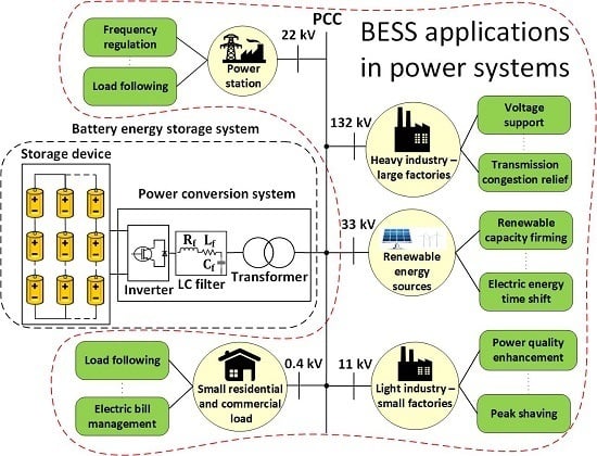
In the context of these challenges, energy storage systems are expected to support the integration of high levels of variable renewable generation and different load schemes, since they are capable of decoupling the timing of generation and consumption [1]. Electrochemical energy storage systems, otherwise known as battery energy storage systems (BESSs), are gaining significant attraction for applications in power systems due to their valuable characteristics, including fast response time, scalability and modularity [1,8,9]. In addition to acting as an energy buffer and mitigating the mismatch between generation and demand, BESSs have the capability of providing numerous ancillary services [8,10].
The term “ancillary services” refers to a variety of control algorithms that allow providing support to the electrical power system with the aim of ensuring the secure and reliable transmission of power to the customers [11,12]. Their importance has grown in the last few years due to the increased penetration of distributed generation. They include voltage support, frequency regulation, transmission congestion relief and peak shaving [13].
BESSs have been used to provide ancillary services at various voltage levels for different stakeholders, which include power system operators, utilities and residential customers. For example, BESSs are used to store excessive generation from RESs; they are deployed at customers’ facilities by acting as “emergency supply”; they are used to defer network upgrade or in energy arbitrage applications [1,11,14]. In addition to the aforementioned services, there is a significant potential for the expansion of use of BESSs to additional emerging applications, including harmonic mitigation and provision of synthetic inertia [7,15,16].
Considering more specifically the UK power grid, an increasing deployment of low carbon technologies (LCTs), i.e., PVs, EVs, heat pumps (HPs) and other smart appliances (SAs) at distribution level is expected in the next decades in order to reach the UK government’s “net zero” target by 2050. Based on the projections published by the UK electricity system operator (ESO), the amount of distributed generation in the UK will continue to experience a steady growth in the future. At the same time, electrification of transportation and heat will lead to a significant increase in load levels [17]. Simultaneously, a large number of BESSs have already been installed in the UK, and they are utilised in a wide variety of ancillary services. However, due to the expected changes in the energy generation and demand patterns, there is a potential for a significantly larger number of installations and new areas of applications. As a result, the UK ESO [17] projects a rapid development of these units in the 2020s.
This paper is intended to provide comprehensive review of the state-of-the-art on BESSs applications in power systems, with a focus on ancillary services provided and the most common technologies. The paper also aims to identify potential future applications relevant to the UK electricity network and more in general to power grids with large numbers of LCTs.
The paper is organised as follows: Section 2 provides an overview of the largest BESS projects in the UK, including those under operational or planning status. In Section 3, an insight into the main battery technologies used in these projects is provided. The aim of Section 4 is to provide a robust classification of the ancillary services currently offered by BESSs, while harmonising the notation found in the literature. Section 5 identifies existing gaps and steps to be taken towards a more effective adoption of these devices into power systems, both from a device and a system point of view. Section 6 draws the concluding remarks.
2. BESS Projects in the UK
A list of BESS projects installed in the UK is provided in Table A1 of Appendix A, based on the UK Renewable Energy Association (REA) and the United States Department of Energy (DOE) database [18,19]. Only projects under operational status are included, while projects that are either announced, contracted or under construction are not listed. Table A1 only shows projects installed at voltages above 11 kV, whereas smaller installations that are connected at the customer level are not included in Table A1. Based on these criteria, at the moment of this writing (May 2020), twenty-four BESS projects have been identified, for a total installed power equal to approximately 25.5 MW.
The projects are listed by decreasing rated power, and for each project, location, technology adopted, ancillary service(s) provided and voltage level are shown. The abbreviations used in the table are listed in the end of the paper. In Table A1, the distinction between primary and secondary distribution is based on the definition provided in [20]. Thus, the term “primary distribution” implies that V > 33 kV, while the term “secondary distribution” is used when the voltage level is V ≤ 33 kV. BESSs are connected to the grid by means of a transformer: in the table, the rated voltage values refer to the high side of the transformer, corresponding to the point of connection (PoC).
Among these projects, the most significant ones are shortly described below, while more details can be found in the references provided:
Project 1 is the largest battery energy storage facility in the UK and Ireland, installed within Kilroot coal-fired generation plant, with the aim of providing frequency regulation for the Irish electricity system (including both Ireland and Northern Ireland), which is characterised by high penetration of onshore wind energy [21].
Project 2 is the Smarter Network Storage project, which aims at investigating various capabilities and revenue streams of BESSs. To this end, a 6 MW/10 MWh BESS is deployed in a 33/11 kV primary substation in Leighton Buzzard [22].
Projects 3, 11, 12, 15, 16 and 17 are part of the Northern Powergrid’s Customer-Led Network Revolution (CLNR) project, which aims at assessing the potential for new network technologies and flexible customer response. For this purpose, six battery storage units are connected at three different locations, representing different grid conditions, with the placements offering a representative sample of 80% of the entire UK power grid. The provided services include voltage support, electric energy time shift and stationary transmission/distribution upgrade deferral [23,24].
Project 6 is of particular interest, since it refers to the deployment of a BESS at the Hywind offshore wind farm in Scotland, which constitutes the world’s first floating wind farm [19]. As detailed in [25], this project presents major opportunities in a wide range of applications, including: capture of wind overshoots, reduction of balancing costs, increase of power market value, and other ancillary services.
Projects 7 and 9 are related to the installation of 250 kWh commercial-scale Li-ion BESS units within solar farms, showing that battery units have the potential to support the effective utilization of solar power and to foster its penetration to the generation mix [19].
Project 8 constitutes one of the first industrial-scale BESS facilities in the UK, with a 300 kW/640 kWh Li-ion BESS being connected to a solar farm in Somerset. One of the aims of the project is to raise awareness on the potential benefits from the deployment of BESSs at the industrial scale among investors and developers. Furthermore, these systems can be utilised by the local distribution system operator (Western Power Distribution) with the aim of enhancing the network power quality [26].
Project 10 refers to five 50 kW/100 kWh BESS units, installed in one of Western Power Distribution’s substations, with the focus being placed on investigating the use of BESSs for deferral of grid investments, and evaluating the use of smaller distributed units across the network against single units deployed at a specific location [27,28].
Project 13 is the first project funded by the Low Carbon Networks Fund (LCNF) that locates the BESS units close to the residential customers, rather than at the substation [29].
Projects 14, 18, 19, 20, 21 and 22 are installed in remote islands, and are functional to the development of renewable-powered microgrids (MGs). The objective of these projects is to reduce the reliance on diesel generators and smooth renewable generation. The services provided by the BESS units include: time shifting of the excess energy generated by RESs during low demand times to high demand times, and electric supply capacity [30,31].
Based on the ratings shown in Table A1, the majority of the projects is installed at the distribution system. This is mostly due to the cost of BESSs with increasing voltage levels. Additionally, the majority of DERs are installed at the distribution system, thus making demand response management more challenging at low voltages and justifying the connection of the battery units.
Regarding the battery technology, lithium-ion is the most deployed, followed by the more mature technology of lead-acid, whereas three of the projects differentiate from this trend, featuring the technologies of Li-ion titanate, vanadium redox flow (VRF) and sodium-nickel-chloride [32,33]. A description of the characteristics of each technology will be given in Section 3.
BESSs have been utilised for the provision of a wide variety of ancillary services [18,19] that are summarised in Table 1. Each one of these services will be described with more details in Section 4 and the numbering used in Table 1 will be referred to later in the paper when each service is described in detail.
The total installed capacity for the most widely deployed services is provided in Table 2. Based on this data, there has been a trend towards utilizing the BESSs for time-shifting applications, including those in which the battery units work in conjunction with RESs. The second most popular application consists in using BESSs for deferring investments for the upgrade of the transmission system (TS) and distribution system (DS). Additionally, BESSs have been utilised for the provision of ancillary services such as voltage support, which is gaining increasing importance due to the growing penetration of variable generation and load patterns into the grid, as highlighted in [4], where a detailed investigation and classification of the solutions that mitigate voltage variation is provided.
It is expected that the number of installed BESS units will increase simultaneously to the reduction of costs. According to [19], a number of projects are at the moment at the planning stage. More specifically, the “Gigha Wind Farm Battery Project” refers to the installation of a 100 kW/1.25 MWh VRF-based BESS within the wind farm in the isle of Gigha, in Scotland. Currently, the power output of one of the installed wind turbines is restricted at a lower value than its nominal rating due to grid constraints. Thus, the primary purpose of the battery unit will be to release the full potential of this turbine, by storing the excess power and delivering it back to the grid under low wind conditions. Further applications under investigation for this project include its use as back-up power supply for the island [34,35].
Another project under contracted status refers to the installation of an Li-ion 20 MW BESS on National Grid’s network with the aim of providing frequency response, a service that is gaining increasing importance due to the phase-out of the conventional coal-fired plants, which results in the reduction of inertia across the UK power grid [36].
3. BESS Technologies
For power system applications two parameters are commonly used to characterise BESS units. The first is the power capability (W), shown in Table A1, corresponding to the rate at which energy can be transferred to or from the battery (this quantity is also referred to as “rated power flow”). The second is the amount of energy that can be stored in the device, or capacity (Wh). These two parameters are not independent of each other: optimising the design in terms of power-to-energy ratio to meet the needs of a specific application (power or energy) leads to more cost-effective solutions [37].
Both characteristics depend on the battery chemistry, and therefore as part of this literature review, the most popular BESS technologies are presented. While a large variety of technologies for rechargeable batteries are available for grid applications, this paper will focus on the ones deployed for the projects presented in Table A1: lead-acid, lithium-ion, sodium nickel chloride and vanadium redox flow.
In the following sections, a brief description of the operating principle of each technology is given. This is followed by a review of the advantages, disadvantages and limitations, while the main research trends, gaps and future developments for each technology are identified.
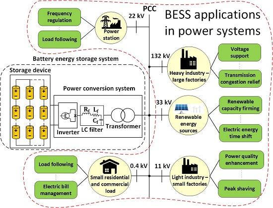
3.1. Lead-Acid
The structure of a lead-acid battery is given in Figure 1. It consists of a positive and a negative electrode, which contain a lead dioxide () and a spongy lead () respectively, with both electrodes immersed in an aqueous sulphuric acid electrolyte () [38].
The two most common types of lead-acid batteries in the market are the vented lead-acid (VLA) and the valve regulated lead-acid (VRLA) [1]. Compared to other battery technologies, lead-acid is the oldest and most mature, featuring low cost due to its widespread application [39,40]. In case of cost-sensitive applications, in which low energy density and limited life cycle are not an issue, while there is demand for roughness and tolerance against misuse, lead-acid batteries are dominating [1]. Additionally, they constitute a good solution for use as backup power source, since their characteristics of long-life and low-cost suit these application, where low duty cycle is required [41].
In addition to the low cost-to-performance ratio, lead-acid batteries present some other advantageous characteristics such as high voltage per cell, good capacity life, acceptable performance at room temperatures and good life cycle under measured conditions [42]. Furthermore, their charging technology is relatively simple, the maintenance requirements are low and they are characterised by large storage capacity [8,43]. Besides, they are spill-proof and easy to transport [44]. Other advantages include: fast response time, small daily self-discharge rate and moderate efficiency, which is higher in advanced designs such as the ones described in [10,45,46].
On the other hand, the drawbacks include their relative bulkiness (low energy density and specific energy [47]), the poor characteristics under low temperature, which increases the cost since thermal management systems are required [10], as well as the fact that the prolonged discharged state leads to their damage [48], with the lifespan being reduced due to sulfation effects [49]. One of the most severe limitations is the low cycling capability (or short cycle number), which may have a negative impact on the economics of the interconnected system in case of utility applications. Other technical issues include: low depth of discharge (DOD), limited lifetime and slow charging [44]. From the environmental point of view, the use of heavy metal components renders this technology toxic and hazardous for the environment [42,43,50,51].
Based on [52], the main research trends for lead-acid batteries include the optimization of the preparation technology of key raw materials, the improvement in the design of the battery structure, the manufacturing process and the applicable range of operating conditions. In addition, there is extensive potential for the advanced lead-acid battery technology, including lead-carbon batteries. The development of such novel technologies paves the way for improvements in terms of energy density and life cycle of lead-acid batteries.
The “ultra-battery” constitutes another promising solution. It combines the benefits of an asymmetric capacitor and advanced lead-acid battery technology, offering, among others, about 50% higher charge/discharge power and three times longer cycle compared to the traditional lead-acid batteries [42].
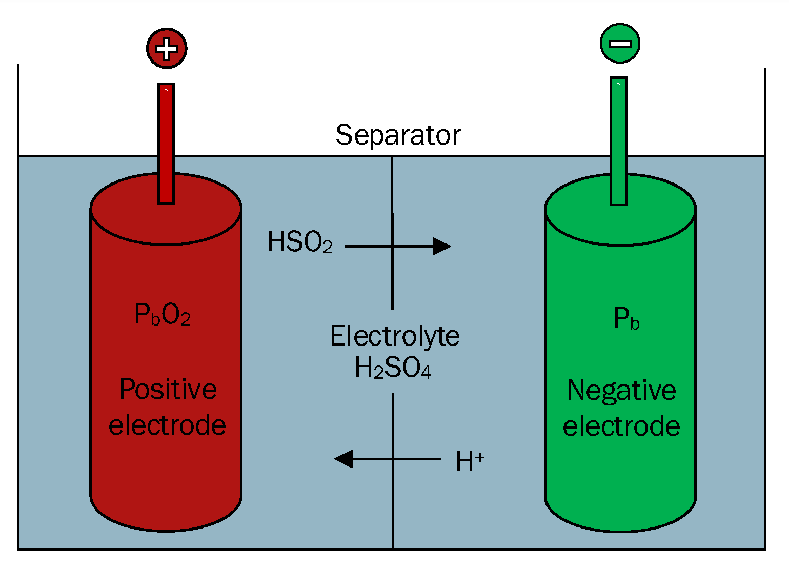
3.2. Lithium-Ion
During the last years, lithium-ion batteries have undergone an increasing deployment in stationary power applications, driven by the significant experience gained from their development in other types of applications, such as electric and hybrid vehicles [38,53]. The typical configuration of lithium-ion batteries is provided in Figure 2. It consists of a positive and a negative electrode, separated by porous polymeric materials and immersed in an electrolyte. The positive electrode contains a metal ion (such as Co, Ni, Mn) and oxygen, the negative electrode is made of carbon material such as graphite, while the electrolyte consists of lithium salts in organic liquid [38]. As illustrated in the figure, lithium ions are extracted from the cathode and inserted into the anode during the charge process, and the reverse reaction occurs during the discharge process.
Li-ion batteries feature the highest energy density, thus offering a huge potential for deployment in a wide range of energy storage systems [54]. Li-ion technology presents other advantages, including high power density, high efficiency, long cycle numbers, low discharge rate as well as no-memory effect [8,45,47,50]. Additionally, Li-ion batteries are characterised by stable discharge voltage, wide operating temperature, high level of safety and they possess a comprehensive cycle efficiency in the range of 85% [43]. Compared to aqueous battery technologies, they are lightweight and present packaging flexibility [41]. Their cathode material is of low cost and they do not have significant environmental impact since the lithium oxides and salts are recyclable [42]. Other important advantages are their high specific energy, the rapidly lowering costs, the excellent charge retention, the high cell voltages, the very good performance at low temperatures and the high DOD [53].
Regarding the disadvantages of Li-ion batteries, one of the main issues is the heating of their internal resistance, which can cause battery’s failure. Thus, overcurrent and overvoltage systems should operate in parallel to ensure appropriate protection [47]. The requirements of internal overcharge protection circuits and special packaging methods increase the battery’s cost [42]. Additional safety issues can arise if the maximum charge voltages are exceeded or a damage of the physical device occurs, resulting in thermal runaway, venting, fire and explosion. Another drawback is the complexity of the charging circuitry and the requirement for individual cell monitoring, since premature discharge cut-off or deep discharge can incur negative consequences on battery capacity. Besides, there are known concerns regarding the availability of adequate resources for large-scale energy storage applications [53]. Environmental issues can also arise due to the fact that lithium is highly reactive and flammable, while some electrodes and electrolytes are toxic [45]. At last, the cycle DOD can have a negative impact on the battery’s lifetime, while they are fragile with their life cycle being temperature-dependent [10,46].
Improvements to the basic configuration have been obtained by adding fibre and nano-composite improvements to the anode. This has allowed achieving higher power, higher reversibility and increased life cycle, while the use of solid electrolytes and electrolyte salts has reduced the acidity and the safety risks [53]. Recent research has focused on changes in the electrolyte and negative electrode, while there exists a lot of potential for improvements in lithium chemistries. In addition, advanced lithium energy storage systems can increase the energy density, due to the use of nanowire silicon in the anode [42,46,53].
3.3. Vanadium Redox Flow
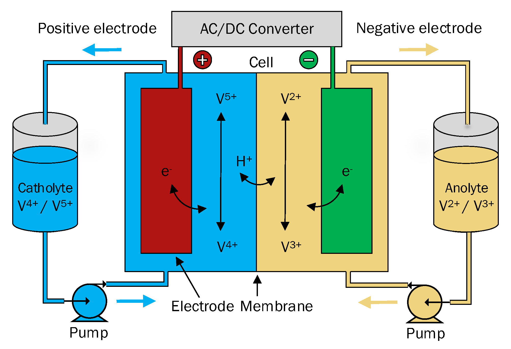
Vanadium redox flow (VRF) batteries are the most widely employed flow batteries. They differ from conventional batteries in terms of storing process, since they utilise two external tanks for the storage of the electrolyte, which is pumped through the electrochemical cells during the process of charging and discharging, as illustrated in Figure 3 [8,55]. These batteries make use of two liquid electrolytes—a positively and a negatively charged—separated by an ion-selective membrane.
One of the most prominent advantages of VRF batteries is the use of vanadium electrolyte, which eliminates cross-contamination issues [45]. Other advantages are: large number of cycles, flexibility in the design of power and energy capacities, low standby losses and simple cell management [8,56]. Compared to other types of flow batteries, they present higher energy densities due to the increased concentrations of vanadium ion. Further advantageous characteristics are the operation at increased current densities and wide range of temperatures, the possibility to provide continuous power with a discharge duration time longer than 24 h, the ability to be brought up to full power promptly and high energy efficiency [10,50,57]. Additionally, VRF batteries do not cause significant safety and environmental issues because they do not employ highly reactive or toxic substances, they have low maintenance cost and can be idle for long time periods without losing their storage capacity [44]. Additional advantages include: large storage capacity, high power output, high energy conversion rate and suitability for large-scale energy storage [43].
An important aspect of BESSs based on VRF technology is the possibility to design power and energy ratings independently, thus optimizing the system’s power acceptance and delivery properties [46]. More specifically, the energy rating depends on the size of the external tanks, while the power rating is a function of the battery properties. Furthermore, an inherent strength of VRF batteries is their very small self-discharge, since the electrolytes are stored in separate sealed tanks [10]. Furthermore, since there are no physical and chemical changes in the electrodes during operation, a more stable and durable performance can be achieved [46]. Since the active materials are separated from the reactive point source, VRF batteries are also safer. Finally, they are tolerant to overcharge and are characterised by deep DOD [42,58].
As far as their disadvantages are concerned, VRF batteries are relatively expensive. In addition, a considerable layout area is required due to their configuration, and they present parasitic losses due to the operation of the pumps, which together with the flow control and the external storage tanks result in high capital and running costs [8,10,54]. Due to the complexity of the system structure, VRF batteries are not suited for small-scale storage applications [42,46,51]. Rather, they are more suitable for peak-shaving and energy time-shifting applications, due to the relatively low energy density of the vanadium electrolyte [38,56,59]. Another drawback is their low performance due to the non-uniform pressure drops and the reactant mass transfer limitation and their high initial self-discharge rate [10,51]. Finally, an additional disadvantage is the high cost of the vanadium electrolyte [45].
Regarding future developments, significant research effort is put on reducing the cost. Furthermore, there is a potential for increasing the storage system’s power density via the use of thinner and more active reaction felts [38]. Additional research activities are focused towards the development of low-cost, efficient and reliable electrodes. Technical challenges that still need to be solved are the low electrolyte stability and solubility, which have a negative effect in the energy density [10]. The design of the diaphragm, which determines the battery life and the conversion efficiency, is another important research area [52].
The concept of redox flow Li-ion battery (RFLB) has been addressed in several publications as a solution to low energy density. Combining the safety and flexibility of the redox flow batteries and the high energy density of Li-ion batteries, RFLB can potentially improve the energy density of redox flow batteries by more than 10 times [60,61]. More recently, various implementations of RFLBs have been proposed: in [62], the authors describe an RFLB which stores energy in Li-ion battery materials while operating as a redox flow battery. The RFLB full cell uses LiFePO and TiO as the cathodic and anodic Li storage materials, respectively, and a conducting Nafion/polyvinylidene difluoride composite membrane. The proposed topology has been shown to achieve high energy density (five times than the one of VRF) and good cycling performance, while improvements related to the membrane’s conductivity and the use of suitable redox mediators render it a promising solution for large-scale energy storage. Ref. [63] presents a novel RFLB half-cell based on the redox-targeting reactions between iodide (I) and LiFePO, having demonstrated high energy density, excellent cyclic performance and potential for lowering the system’s manufacture and maintenance cost. Improvements of the flow design and conductivity can make the Li-I RFLB a strong candidate for large-scale applications.
3.4. Sodium Nickel Chloride
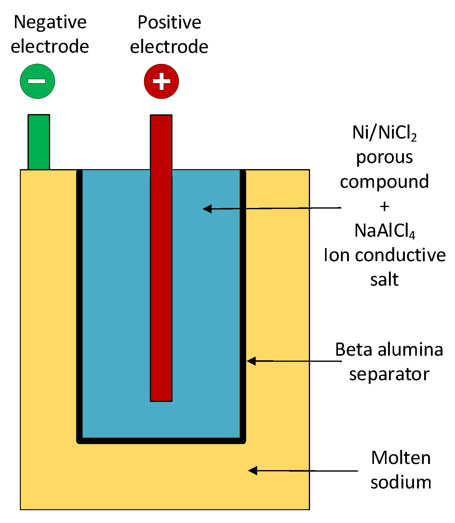
The sodium nickel chloride (), also known as “Zebra” battery, belongs to the broader family of high temperature batteries, operated at temperatures between 280 °C and 350 °C . The ionic conductibility of their ceramic electrolyte increases with temperature, which also justifies why the anode and cathode are in molten state during their operation [64].
Figure 4 shows the typical configuration of a battery. The cathode consists mainly of nickel (Ni) and sodium chloride (NaCl) and the anode is made of sodium (Na). The electrodes are separated by a beta-alumina ceramic wall [38,45].
batteries are characterised by high energy density, they present long life cycle and are practically maintenance-free [8]. Due to the characteristics of long life cycle, long discharge time and fast response, they are well suited to applications that engage bulk energy storage such as the ones within transmission systems, railway transportation and large renewable energy plants [44]. This claim is further expanded in [64], where the high suitability and compatibility of the electrical characteristic of this battery (e.g., its volumetric and gravimetric energy densities) with large-scale stationary storage is highlighted. Compared to the nickel cadmium (Ni-Cd) and nickel metal hydride (Ni-MH), they feature higher efficiency, in the range of 90% [42].
Compared to other types of high temperature batteries, they possess inherent overcharge capabilities and lower operation temperatures. In addition, their power-to-energy-ratio is flexible, and their cooling to ambient temperatures does not cause damage to their components [38].
Within their drawbacks are their high cost and self-discharge [50]. The main limitation for the use of batteries is the required heat to keep the molten state temperature.
Furthermore, some researchers have expressed concern due to the reaction of the molten sodium with water, which can cause fire [44]. However, based on the safety tests under operating, abuse and failure conditions performed in [64], it is concluded that this technology possesses inherent safety features, which is of critical importance for large-scale energy storage deployment in the high voltage network.
3.5. Summary of Battery Technologies
Table 3 summarizes the main advantages and disadvantages of the main battery technologies currently deployed for power systems applications.
A summary of the main characteristics of the technologies described above is provided in Table 4. The characteristics considered include: power and energy rating, life cycle, life span, efficiency, energy and power density, response and discharge time, energy and power capital cost. For each metric, a range of variability is provided, based on the references listed.
For some characteristics, such as power ratings, there is a clear advantage of some technologies versus others: more specifically, Pb-acid and Li-ion batteries are characterised by higher power ratings. For other characteristics, such as efficiency, the performance of various technologies is closer, since efficiency values higher than 90% have been reported for all of them. For some other characteristics, such as the energy density of Pb-acid energy storage, a significant variability is observed. This may be due to different manufacturing processes or test conditions.
Based on the results shown in the summary table and the technology review carried out above, one can conclude that BESS energy technology is changing rapidly. Thus, it is likely that in the future more diversified types of batteries will be deployed for transmission and distribution applications, while at the moment the great majority of projects listed in Table A1 are deploying Li-ion batteries.
4. Ancillary Services Provided by BESSs in Power Systems
This section will provide a description of the most common ancillary services provided by BESS projects in the UK, and presented in Table 1. To this end, different sources have been utilised, including databases and peer-reviewed academic publications. These were supplemented by grey literature, i.e., technical reports and white papers from agencies, research and development laboratories and organisations and private companies, since grey literature features up-to-date research knowledge on the topic of battery energy storage, which constitutes a fast-paced industry.
Based on the existing literature, the terminology used for ancillary services and their classification varies broadly [69]. A commonly employed approach to classify these services is based on the power rating of the system and the discharge time [70]. Under this approach, services are divided into power and energy applications, depending on if their discharge duration is less or more than 30 min respectively [67,71,72].
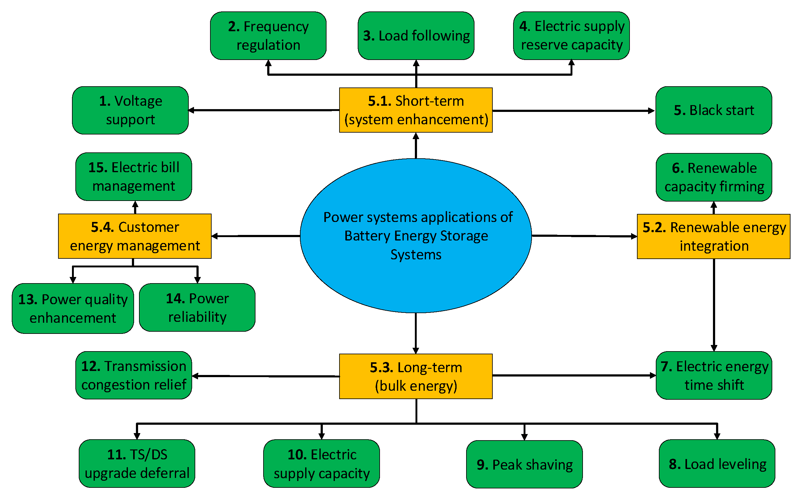
In this paper, an alternative approach is adopted, based on the work presented in [11], because it is deemed more appropriate to categorise the ancillary services provided by BESSs in the UK Therefore, ancillary services are divided in four families:
- Short-term (system enhancement): to ensure the stability, robust operation and reliability of the electrical grid via the provision of rapid-response services, responding to small-time scale (seconds to several minutes) fluctuations in generation and demand.
- Customer energy management: to enhance the power quality of a specific part of the grid by mitigating short-term power delivery issues, e.g., supply interruptions and voltage dips.
- Long-term (bulk energy): to boost the system’s efficiency and reduce the electricity costs by providing services that operate over a long period of time, which can be several hours.
- Renewable energy integration: to enhance the energy-efficient and cost-effective penetration and operation of RESs into the grid. This can be achieved by smoothing the output and control the ramp rate of RESs in order to eliminate rapid voltage and power swings on the grid. Since this paper is focused on the UK, where RESs are gradually overtaking the coal-fired generation, it seems reasonable to consider the renewable energy related applications as a distinct family of applications [1].
Figure 5 illustrates the four main families of ancillary services listed above. For simplicity, each one of the ancillary services listed in Table 1 is associated to one family, although the authors recognise that some services could have been associated to more than a family.
In the following sections, a more detailed description of each application family and of the corresponding services is provided.
4.1. Short-Term Applications
The first family includes services which are characterised by fast response, and that mostly are based on compensating unbalance between generation and demand.
4.1.1. Voltage Support
The equipment used for generation, transmission and use of electric power presents inductive or capacitive behaviour, causing reactive power flow on the grid. By providing voltage support, the grid operators aim to offset reactive power flow and ensure that the voltage is restored or maintained within acceptable limits, and therefore guaranteeing system stability [19,73].
BESSs provide voltage support by performing as dynamic reactive power supplies, injecting or absorbing reactive power in the distribution and transmission systems. The ability of the control system algorithm to react immediately to the variation of the voltage renders them suitable for this application. Additionally, the four quadrant operation of the power converter units enables BESSs to continuously control the reactive power almost independently of the real energy being stored.
4.1.2. Frequency Regulation
Deviations of the grid frequency are caused by the mismatch between generation and load [73]. BESSs respond to an increase or decrease of the grid frequency by charging or discharging, thus contributing to maintaining the grid frequency within preset limits.
The term “load following” can be used equivalently. According to [19], the resources performing “load following” function change their output in response to the changing balance between electric supply and end user demand within a specific region or area, over time frames ranging from minutes to a few hours.
The high suitability of converter-based energy storage for such applications is due to their rapid response to load changes, since they can react to power fluctuations on a millisecond time scale, compared to the majority of generators, whose reaction time varies from a few seconds to several minutes [49]. In addition, they allow both load following “up” and load following “down” since they can charge and discharge, respectively [13].
4.1.3. Electric Supply Reserve Capacity
A spinning reserve is defined as a part of the system capacity that is not used in normal operation. A BESS acts as spinning reserve if it is maintained at a level of charge, with the aim of responding to a generation or transmission outage (Conversely, a non-spinning reserve capacity is offline and it is not synchronised with the grid frequency. It can be made available within ten minutes and it is used after all spinning reserves are online [73]. BESSs do not belong to this category).
Depending on the application, the response time of BESS varies from milliseconds to minutes, supplying power to maintain continuity of power delivery, while back-up generators are started and brought online. As a result, utilizing the BESSs for the provision of this ancillary service can render the presence of back-up generators running idle unnecessary [74].
4.1.4. Black Start
Black start refers to the ability of a generating unit to start without an external electrical supply and it is essential for the reliable restoration of the grid following a blackout [19].
4.2. Long-Term Applications
Bulk energy applications refer to the storage and use of large amounts of energy with the aim to achieve a more efficient and cost-effective power system operation.
4.2.1. Electric Energy Time-Shift
The application of electric energy time-shift, also known as energy arbitrage, involves the purchase of electric energy in periods of low system marginal cost or prices to charge the BESS, and consume or sell the stored power at a later period, when the prices or costs are high.
Similar time-shift operation can be performed by the BESS by storing excess energy produced by RESs such as wind turbines and photovoltaics, which would otherwise be curtailed during periods of overproduction [73]. In the latter case, the service is referred to as “renewable energy time-shifting”, which essentially is centralised or distributed electric energy time-shifting linked to renewable generation [19]. If energy storage is used to time-shift renewable energy for end-use costumers that generate renewable power on-site, the service is termed “on-site renewable generation shifting” [19].
A very similar service is the one referred to as “load levelling”. This service refers to the process of storing power during periods in which the system’s load is low, and delivering it back to the grid when the demand is high. In this case, the power supplied by the BESS results in reducing the load on less economical peak-generating facilities. Therefore, deploying the BESS allows deferring investments on new generating capacity and on TS/DS upgrade. The latter service will be analysed in Section 4.2.4 [75].
4.2.2. Electric Supply Capacity
4.2.3. Peak Shaving
Peak shaving is intended to avoid the installation of generating capacity by making use of the BESS to supply peak loads with high variability. The advantages that derive from this application are numerous. Firstly, the decrease in the peak demand results in the reduction on the electricity bills of the commercial and industrial customers. Additionally, it has a positive impact on the utility side, since the need for the use of peaking units is reduced, thus reducing the operational cost of generating power during these periods. Lastly, since it causes the loads to be flatter with smaller peaks, investments in additional infrastructure are delayed [75].
4.2.4. TS/DS Upgrade Deferral
This service refers to delaying or avoiding the replacement or retrofitting of existing transmission and distribution equipment. This can be achieved by means of small amounts of energy storage, able to provide adequate incremental capacity in order to defer the investments in new infrastructure.
Among the benefits arising from this application are: decreased costs for the ratepayers, improved utilisation of the utility assets, allocation of the capital for other projects and decreased financial risk related to the investment. Concurrently, the equipment’s life can be extended, which may be of critical importance for equipment such as ageing transformers or underground circuits whose replacement or upgrade is costly [13].
4.2.5. Transmission Congestion Relief
Transmission congestion can arise during periods of peak demand. One mitigation to this problem consists in costly investments in infrastructure to increase the transmission capacity. This cost will then be translated in higher transmission access charges, increased use of congestion charges or locational marginal pricing for wholesale electricity at certain transmission nodes.
The aforementioned costs can be evaded by installing an energy storage system. More specifically, the energy storage is installed downstream from the section of the transmission system that is congested. The energy storage charges under lack of transmission congestion and discharges under periods of peak power demand, in order to alleviate the electric transmission congestion [19,73].
4.3. Renewable Energy Integration Applications
In this family of applications, a BESS is used with the aim of facilitating the integration of RESs and ensure their smooth operation. These applications are similar to other ones used for more general purposes, however, in this paper a different category is created to highlight that BESSs can be beneficial to renewable resources integration.
Renewable energy integration applications considered in this section are: renewable capacity firming and time-shifting [11]. In this section, only capacity firming is described, since time-shifting has been already described in another subsection (i.e., Section 4.2.1). Both applications are shown in Figure 5.
Renewable Capacity Firming
This service refers to the use of energy storage to smooth the output and control the ramp rate of a renewable generation plant, with the aim of mitigating abrupt voltage and power swings on the electrical grid. The latter are caused by phenomena such as wind gusts or rapid changes of irradiance due to clouds. Essentially, the variable and intermittent renewable generation can be maintained at a committed level for a period of time, since these rapid output changes are offset by other dispatchable generation [19,75].
4.4. Customer Energy Management Applications
This group of applications refers to the utilisation of BESSs to deliver power to the customer in a reliable manner and in accordance with power quality standards. In addition, the storage units can offer services that create economic benefits for both costumers as well as system operators and utilities [1]. The three main services that fall into this category of applications are explained in the next sections.
4.4.1. Power Quality Enhancement
Storage units can be utilised in order to enhance the power quality and protect the customer’s loads against events of short duration. These events include variations in voltage magnitude or/and frequency, low power factor, harmonics and interruptions in service. To mitigate these events, the BESS discharges in order to smooth out the disturbance, with its typical discharge times ranging from a few seconds to a few minutes [73].
4.4.2. Power Reliability
Under an event of utility power outage, a BESS can provide support to the customer’s load for a time duration which depends on the energy capacity of the storage system relative to the load size. On-site generator sets, e.g., diesel generators, can be added to extend this time and support the load for outages of longer duration. The BESS may belong either to the customer and be under his control, or to the utility. In the latter case, the storage system has a twofold scope, since it can be utilised from the utility for the reduction of demand in addition to serving the customer’s needs [73].
4.4.3. Electric Bill Management
This service is aimed at reducing customers’ electric bills [19]. The deployment of storage systems behind-the-metre enables shifting the electricity purchase from hours when time-of-use (TOU) prices are highest to periods of lower rates, thus resulting in the reduction of the customer bills. In this case, the provided service is termed “time-of-use bill management”.
The “demand charge reduction” service results in the same effect, since the storage units are smoothing the load profile in order to reduce the peak demand charge of the customer [1]. When the energy storage is used in conjunction with RESs, the application is referred to as “electric bill management with renewables” [19].
4.5. Location of Applications within the Power System
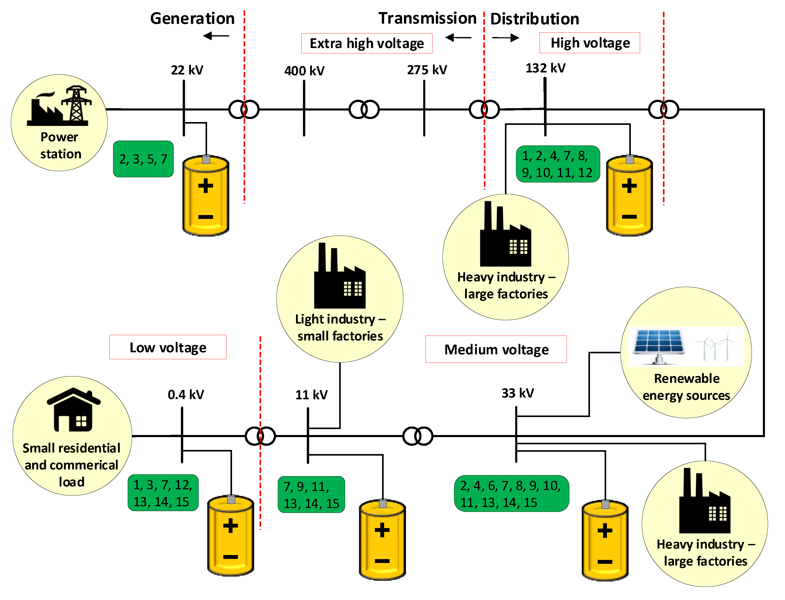
Figure 6 presents a simplified representation of the UK electricity network, including electricity generation, transmission and distribution (primary and secondary), interconnected loads and BESS units. The figure illustrates the location of each application within the electrical grid [69,76]. The different ancillary services are referred to by using the numbers provided in Table 1.
Each ancillary service may be deployed at different locations in the power system, although some applications may be more specific for certain voltage levels. For example, electric bill management is expected to be deployed at lower voltage levels, close to the customers. However, the figure highlights the flexibility and wide-spread applications of both BESSs and ancillary services.
The next section will describe opportunities for further development of these applications.
5. Future Applications and Research Gaps
Based on the recent trends and expected developments of power systems in the future, BESSs have a lot of potential to improve grid operation and to help the transition to the smart grid.
In the next sections, the most promising applications are described. These applications are not limited to the UK, but may be of interest in other countries, where similar challenges may exist.
After describing existing and future ancillary services provided by BESSs, more general research gaps will be presented. These aspects are important to enhance the performance of BESSs and facilitate their integration into the power grid.
5.1. Virtual Inertia Provision
Since conventional generators have been phased out and replaced by RESs, power system inertia has been decreasing, thus threatening the system frequency stability.
Inertia is an inherent property of power systems including conventional power plants, due to the kinetic energy generated and stored in the rotating parts of synchronous generators (SGs), which is released in case of disturbances to keep the frequency within safe operating limits [16]. On the other hand, power converters decouple the energy sources from the grid, and thus they do not provide inertial response [77].
Especially for the UK power system, which is not synchronised with the continental European power grid, and is expected to accommodate increasingly large amounts of RESs in the next decades, the decrease of power system inertia is becoming a concern for the transmission system operator (TSO) [78]. For example, the decrease in system inertia may result in undesirable operation of rate-of-change-of-frequency (ROCOF) relays, which are widely used in the UK, thus increasing the risk of loss of supply [77,79].
The above concerns can be mitigated by implementing a novel ancillary service known as “virtual inertia” (or “synthetic inertia”). BESSs could be used to mimic the inertial response of SGs as follows: the interface converters could be controlled to reproduce the generator dynamics, and the battery would provide the energy for controlling the active power output. Due to their capability to regulate the active power output very fast and precisely, BESSs are very well suited for this application, constituting a promising alternative to enhance frequency stability in low-inertia power systems [7].
Virtual inertia can also be provided by RESs. Several control strategies that enable wind turbines to provide emulated inertial response have been proposed in the literature. In [80], a complementary control loop to emulate inertial response for variable speed wind turbines is developed by adding a frequency dependent torque component to the reference torque, obtained from the maximum power point tracking (MPPT) algorithm. A torque limit-based scheme that maximizes the inertial response accounting for the maximum torque limit is presented in [81]. A modified version of this method is developed in [82], achieving reduced mechanical tensions on the turbine, accurate inertial response estimation of a wind farm by using its total generation, and more secure system operation. The provision of emulated inertial response by wind turbines by means of droop control strategy is discussed in [83], where it is shown that the tuning of the control parameters depends both on the power system configuration and wind power penetration level. A distributed control method combining droop and inertial control is presented in [84], where the wind farms participate in the power system’s primary frequency regulation, and the power sharing among them is optimized through an iterative algorithm.
Limited research has been done on PV systems providing frequency support. Ref. [85] proposes a novel control strategy for a three-phase PV system, which combines two control strategies: voltage control of the DC link capacitor and a derating of the PV power output. The latter is achieved by operating the DC link at higher voltage than the one obtained from the MPPT control, thus reducing the power output and therefore allowing more flexible operation of the PV unit to compensate frequency fluctuations. A virtual inertia control for PVs in an islanded DC MG is described in [86], where the MG’s dynamic performance is improved by controlling the PV active power. In [87], a BESS, integrated in the DC link of a PV inverter through a DC-DC converter, is controlled to emulate a capacitance, thus increasing the system inertia. A novel solution that transforms a grid-following PV system to a grid-forming one, without any hardware and software modification of the PV inverter, is presented in [88]. In this work, a supercapacitor-based ESS, placed in parallel at the AC side with the PV, is controlled to smooth the PV power fluctuations, as well as to supply inertia. More recently, machine learning-based virtual inertia synthesization control strategies for PV systems based on synchronverters have demonstrated promising performance [89].
A frequency derivative-based inertia emulation method for BESSs is introduced in [90]: the converters’ active power references and the frequency derivative signal, which is estimated by a frequency-locked-loop, are proportionally related, thus achieving inertia enhancement and improvement of frequency nadir and ROCOF during severe frequency deviations. In [16], the impact of including inertial emulation control of a transmission-system connected BESS on the frequency response is evaluated. Ref. [7] presents the control of a BESS to provide both inertia and primary frequency control, and highlights the important role of BESSs in contributing to frequency stability in low-inertia power systems. This research area at the moment is still in the infancy but appears very promising for power systems with high amount of RESs.
5.2. Enhancement of Distribution System Resilience
As defined in [91], resilience is “the ability to prepare for and adapt to changing conditions and withstand and recover rapidly from disruptions. Resilience includes the ability to withstand and recover from deliberate attacks, accidents, or naturally occurring threats or incidents”. In this context, there is an increasing research focus on the utilisation of DERs with the aim of boosting the resilience of the distribution grid, which has been reflected in many recent literature works.
More specifically, [91] presents a resilience-based design approach for a VRF-based BESS in advanced distribution grids, showing that improved selection of its power-to-energy ratio leads to improved resilience. The paper includes the collection of actual hardware-characterised dynamic data, thus describing an accurate response of the BESS.
In [92], the concept of transportable energy storage systems (TESSs) is presented. This research is the first one to consider the joint scheduling of TESSs and network reconfiguration with MGs to restore the operation of the distribution system after the occurrence of a black out. The developed model, which is tested in a modified 33-bus test system, shows that the resiliency of the distribution system with TESSs is improved compared with conventional ESSs, since a reduction in the total system cost is achieved.
In [93], the equivalent term of mobile energy storage systems (MESSs) is used. The units can be moved and connected at different system buses by the use of a truck and provide various localised services. The paper proposes a day-ahead energy management system (EMS) for a MESS so that the distribution network operator (DNO) minimises the day-ahead cost of the power imported from the grid, while the unit provides voltage regulation at the same time. Although the specific research work is not directly linked to the enhancement of resilience, it shows the potential of the MESSs to provide multiple benefits for the grid.
Finally, [94] highlights the contribution of strategically-placed MESSs and timely disaster forecast to the prevention or mitigation of critical failures in the grid. This paper develops an optimisation model, which identifies the economically optimal location for the battery units during normal operation. The installed units are then moved between different buses to form dynamic MGs and to prevent load shedding during disasters. The paper shows that this approach results in the reduction of the operating costs and the amount of load shedding that is caused by natural disasters, compared to the cases where stationary energy storage units or no energy storage units are deployed.
The aforementioned research works highlight the central role that BESSs are expected to hold in terms of maintaining the robustness and resilience of the future distribution networks. Mobile BESSs seem to gain significant attraction due to their advantages in terms of transportability, operational flexibility and installed capital cost, which is expected to fall in the coming years, rendering them a strong competitor against other distributed generation units [92].
5.3. Implementation of Active Filtering Function
The rapid growth and interconnection of power electronics based RESs and non-linear loads result in an increase of current harmonic content, which causes grid voltage distortion. A mitigating solution to this problem is the use of active filters (AFs). However, they are characterized by significant capital and operating costs and the commercially available products are not suited for low voltage (LV) power distribution systems [95].
Due to the aforementioned disadvantages, the provision of active filtering as ancillary service has increasingly been considered in the literature. This service can be provided by various devices that are connected to the grid by means of power converters.
As an example, [15] presents the control of a three-phase stand-alone inverter to reduce the harmonic content in the grid and to mitigate voltage unbalance. In [6], a PV inverter is controlled to provide active filtering as ancillary service when the PV generation is curtailed, while a novel algorithm is incorporated to ensure that the converter operates within its nominal ratings. The deployment of such functionality may be remunerative for a PV developer, provided that a compensation scheme is given, which could compensate for the revenue losses due to the PV power curtailment. A similar control concept has been applied to wind power generator power converters [96,97,98,99,100].
A more recent work can be found in [5], which describes the use of a STATCOM converter as AF. This project has been developed as a collaboration between one of the UK distribution network operators and a power electronics manufacturer. The paper shows fields results from the retrofitted STATCOM unit installed in close proximity to a wind plant, and demonstrates that this functionality can prevent the disconnection of a wind power plant in the presence of undesirable harmonics generated from external sources.
Based on the above examples, the implementation of active filtering is gaining attention within power utilities. Due to the increasing number of BESSs deployed into the power system and the use of a power converter to interface these devices to the power grid, they represent a promising solution for proving this control technique.
5.4. Voltage Unbalance Mitigation
In light of the increasing penetration of single-phase loads and sources into the grid, such as PVs and EVs, voltage unbalance issues are expected to be exacerbated. Thus, the next generation of grid codes should consider compensation of this effect in steady-state and transient system operation [101].
Voltage unbalance has been traditionally tackled by power system operators by trying to distribute equally the loads on the three phases, by using delta-connected systems, and by applying transposition on long lines. When these mitigating solutions are not viable, active filters can be deployed [95,101]. More recently, unbalance compensation can be achieved by controlling power electronics interfaced DGs, since their converters are not operating at full power continuously. As a result, the available rating can be used for mitigating grid voltage unbalance, as presented in [101].
The majority of control strategies found in the literature are implemented in either three–phase voltage source converters (VSCs) or current source converters (CSCs) [100,102], whereas the unbalance compensation by single–phase devices is addressed in only a few references. In [103], single–phase and three–phase PV inverters are managed by a central controller, which calculates the active and reactive power reference values required from the inverters to mitigate voltage unbalance. In [104], the reactive power provided by single–phase plug-in hybrid electric vehicle (PHEV) chargers is controlled to achieve unbalance mitigation. In [105], single–phase DG inverters are controlled without modifying their active power production. The reactive power references are the outcome of an optimization function that minimizes the negative and zero current sequence components.
Low-power BESSs may provide unbalance compensation since they are generally single-phase connected. In [106], a single-phase BESS is connected to an experimental three-phase LV distribution network, incorporating an interconnected single-phase PV and loads, with the aim of mitigating the network voltage unbalance and reduce losses.
The literature review performed has shown that there is still room for further application of BESSs for unbalance compensation, since this is a relatively new research area. However, in contrast with active filter operation, compensation of voltage unbalance involves charging and discharging of the energy storage unit, and may have an impact on the state of charge (SOC) and the lifetime of the battery [107]. This issue is common to other ancillary services and will be described more in details in Section 5.6.
5.5. Coordination and Optimisation of BESS Units
With the increase of BESS installations, coordination between units, with other devices, and with a central controller will gain importance. In the context of the smart grid concept, coordination can be realised with the utilisation of advanced metering infrastructure provided by smart sensors and metres [4]. As a result, increased power quality, grid efficiency and stability will be ensured through the coordinated control of DGs, BESSs and end-user loads, that can respond rapidly to voltage deviations.
A smart coordination scheme of multiple BESSs is proposed in [108], with the aim of controlling the voltage in a distribution network with high penetration of PVs. The results show that an effective mitigation of overvoltage and undervoltage issues can be achieved, preventing reverse power flows into the medium voltage network and reducing the power drawn from it, which lowers the stress placed into the network infrastructure.
In [109], a control scheme coordinating BESSs, on-load tap changer (OLTC) transformers and step voltage regulators is proposed, resulting in: reduced number of operations of the tap changer during high PV penetration, decreased transmission and distribution losses and improved battery life by limiting the DOD.
Approaches such as the ones described above require coordination of numerous compensation devices, which might bring other disadvantages, such as increased cost, difficulty to control and reduced efficiency due to numerous switching operations. Therefore, [110] introduces a novel coordinated control concept for distributed BESSs, where a main control centre is in charge of neighbouring battery units. The authors compare the performance of the proposed control strategy against a control scheme that features uncoordinated control of BESSs and use of OLTC.
The proposed method is shown to achieve enhanced power quality, i.e., the load factor is improved, and smaller voltage and frequency deviations are obtained. At the same time, the number of charges and discharges are reduced, which translates to extended lifetime and decreased capital cost for the battery units.
Finally, another important coordination aspect is balancing the SOC among multiple BESSs, in particular as the size of the batteries increases. As a result, there is need for deploying more efficient control strategies to achieve optimal dispatching and lifetime management of the units. In [111], the authors answered these challenges by proposing a distributed equalisation strategy, which is deployed in an interconnected distributed battery management systems (BMSs) and aims to balance the SOCs. In contrast to conventional centralized approaches, which present the drawbacks of increased computational burden and communication latency that might result in unbalanced operation, the experimental results show that the adopted approach achieves unification of the SOCs across the distributed batteries to an identical level, which is restored even when a fault occurs in one of the batteries. Thus, the proposed strategy is able to ensure balanced operation and improved robustness.
5.6. Impact on State of Charge and Battery Lifetime Enhancement
The impact of implementing ancillary services on state-of-charge (SOC) is an important aspect of BESS operation that should be taken into account when designing a new BESS installation and its associated ancillary services.
The two main factors that contribute to battery degradation are the frequency of cycling and the DOD [107]. Some services, such as reactive power compensation, do not affect the above quantities, since they do not affect the active power flow. Services provided in the frequency regulation market require high frequency of cycling and low DOD. On the other hand, services provided in the energy arbitrage market, such as load shifting, require low cycling frequency and deep DOD [107]. Therefore, each service will have a different impact on the life span of the BESS and on its performance.
In [112], the impact of implementing three ancillary services (primary control reserve, peak shaving and uninterruptible power supply, UPS) on the ageing of an Li-ion BESS prototype is evaluated using a semi-empirical model that calculates two types of battery ageing: calendar (when the battery is in idle condition) and cycling (when the battery is charged and discharged). This paper shows that the primary control reserve service leads to the highest fade in BESS capacity due to the long operating time.
In [113], the authors highlight the necessity to have accurate information about a battery’s degradation in order to operate the battery efficiently and guarantee that the unit will successfully deliver a service throughout its life. More specifically, information about degradation of the two main performance parameters, i.e., capacity and power capability (Section 3), is the focus of this research work. A lifetime model of lithium iron phosphate batteries is developed with the aim to investigate the degradation of BESS units subjected to a field measured mission profile. To this end, two inputs are given to the developed model: the SOC and temperature mission profiles, which have been measured for batteries providing frequency regulation in the Danish energy market. This paper concludes that capacity is the parameter that limits the most the battery lifetime. The capacity fades mostly due to calendar ageing, which is accelerated when the battery is idle at high SOC levels. The lifetime can be enhanced by decreasing the idling SOC level, however this approach will affect the revenues obtained from frequency regulation service since less power will be bid in the market.
More recently, the integration of hybrid ESSs into DERs has been proposed to facilitate the implementation of ancillary services such as inertia emulation, black start, or power oscillation damping [114,115]. The authors of [115] propose a device that combines the large storage capacity of electrochemical batteries and the high dynamic performance of the supercapacitors. The system is controlled to provide frequency support, and a power sharing control strategy is implemented such that the supercapacitor bank delivers the high-frequency component of the demanded active power, while the battery injects the average power. The computational and experimental results show that this control scheme achieves reduced variation in the battery voltage, discharge capacity and SOC. As a consequence, less stress is experienced by the battery during its operation, which results in improved lifetime and eliminates the need to oversize the battery capacity with additional branches in parallel.
A control scheme that aims at extending a battery’s lifetime and reducing its size is presented in [116]. A coordinated control strategy is developed for the provision of frequency regulation from a system including a wind power plant and a BESS. The latter is used as the secondary resource to share the frequency regulation burden. An adaptive SOC-feedback control is designed to maintain SOC at an optimal value. Based on the simulation results, lower values are obtained for the rate of charge, rate of discharge and DOD, compared to the case where the BESS takes full responsibility to regulate the frequency. In addition, the SOC is kept within an optimal range, thus resulting in an extension of the battery’s lifetime.
Based on the above, when planning a new BESS installation, it is important to consider not only the potential revenues gained from the ancillary services provided on the short term, but also the consequences on the battery ageing and depreciation in the long run.
In line with this requirement, [107] proposes a novel whole-life-cycle planning method for a BESS, with the aim of balancing the revenue and battery lifetime, considering the impacts of battery operation and cycling on its life span. More specifically, the BESS is initially used for primary frequency regulation services in the reserve market and, after a certain degradation of its capacity, it is transferred to load shifting services in the energy arbitrage market. Comparing the results of this approach with the cases where the BESS is used to provide a single service or stacked services, it is shown that a balance between maximizing revenue and extending battery life duration is achieved, thus also reducing the environmental impact caused by battery recycling due to its frequent replacement.
The literature review has shown that more research is needed to optimise profit and battery life duration. Additionally, the impact of various services on battery life and performance is still not well understood, in particular taking into account that different battery technologies, such as the ones described in Section 3, exhibit different performances when subject to the same charge/discharge cycle.
5.7. Remuneration for Each Service
At the moment, it is still lucrative to perform certain type of ancillary services such as “load following” because of the relatively small number of energy storage units installed and providing these functionalities. However, it is expected that in the future, the remuneration for each service provided will decrease. In this sense, [117] shows that when more DERs provide the same service in a given portion of the grid, the marginal value decreases.
At the same time, it is expected that new ancillary services will become more remunerative: for example, with the decrease of system inertia, services related to frequency regulation will be sought. This is specifically relevant for the UK power grid, that is not synchronised with main continental Europe (Section 5.1). Although providing virtual inertia may not be currently remunerated in the markets, it possesses a potential high value by contributing to the avoidance of load curtailment and the associated high costs for end users [118].
Several research works have shown that there is a need for reconsideration and improvement of the pricing and reward structure in relation to ancillary services provided by BESSs. As an example, [119] presents a cost-benefit analysis of an Li-ion-based BESS in a distribution network, with the operation of the battery unit being optimized to provide load-shifting to the end-user. The analysis is based on real-life load data and a proposed technique for forecasting electricity prices. The results show that no profitability is achieved from the investment in the BESS, highlighting that the current trends of market price and electricity tariff structure should change to benefit not only the distribution grid owners but also the BESS owners.
6. Conclusions
This paper presented a comprehensive review related to ancillary services provided by BESSs in the UK Twenty-four projects were identified, mostly connected at the distribution system levels, and currently in full operation.
A qualitative description of advantages, disadvantages and future developments of the most common battery technologies deployed within these projects was performed. The literature review showed that there is room for further research in the deployment of VRF and sodium nickel chloride batteries into the grid, with the latter constituting a very promising alternative to Li-ion for large-scale energy storage.
The ancillary services offered by the BESSs were classified into four families, and a comprehensive explanation of each service was provided. While the authors recognise that other classifications could have been implemented, this paper achieved the objective of harmonising and clarifying the differences and similarities between different ancillary services and to identify a classification suitable for the UK
In Section 5, emerging applications for BESSs were listed. BESSs are likely to play a key role in the future developments of power systems. They will support the integration of RESs and new load patterns by providing several ancillary functions such as: providing synthetic inertia, increasing grid resiliency and mitigating power quality issues, such as voltage unbalance and harmonics. In the context of the smart grid concept, coordination and optimisation between different units providing ancillary services need to be investigated more closely, such that an improved performance is obtained both at the device and system level, leading to a more cost-effective and energy-efficient grid operation.
Finally, interdisciplinary research gaps that are not strictly related to power system engineering were introduced. More specifically, further research is needed to understand the impact of ancillary services on the SOC and on the lifetime of BESSs for each technology, with the aim of extending the battery lifetime and boosting the economic viability of BESS projects. From a financial and policy perspective, the remuneration of ancillary services will have a large impact on their provision and on the overall impact on grid operation.
The discussion above led to the conclusion that, while BESSs are among the technologies that will gain a central role in the future power grid, several research aspects still need to be investigated in order to optimise the use of these devices and exploit their potential.
Author Contributions
Conceptualization, I.M. and G.T.; methodology, I.M. and G.T.; investigation, I.M.; resources, I.M. and G.T.; data curation, I.M.; writing, original draft preparation, I.M.; writing, review and editing, I.M. and G.T.; supervision, G.T.; project administration, G.T.; funding acquisition, G.T. All authors read and agreed to the published version of the manuscript.
Funding
This research was funded by EPSRC (Engineering and Physical Sciences Research Council) Grant Number EP/T013206/1.
Conflicts of Interest
The authors declare no conflict of interest. The funders had no role in the design of the study; in the collection, analyses, or interpretation of data; in the writing of the manuscript; nor in the decision to publish the results.
Abbreviations
The following abbreviations are used in this manuscript:
| AF | Active filter |
| BESS | Battery energy storage system |
| CLNR | Customer-led network revolution |
| DER | Distributed energy resource |
| DG | Distributed generation |
| DNO | Distribution network operator |
| DOD | Depth of discharge |
| DOE | Department of Energy |
| DS | Distribution system |
| EASE | European Association for Storage of Energy |
| EMS | Energy management system |
| ESO | Electricity system operator |
| EV | Electric vehicle |
| HP | Heat pump |
| LCNF | Low Carbon Networks Fund |
| LCT | Low carbon technology |
| Li-ion | Lithium ion |
| LV | Low voltage |
| MESS | Mobile energy storage system |
| MG | Microgrid |
| MV | Medium voltage |
| Na | Sodium |
| NaCl | Sodium chloride |
| NaNiCl | Sodium nickel chloride |
| Ni | Nickel |
| Ni-Cd | Nickel cadmium |
| Ni-MH | Nickel metal hydride |
| Lead acid | |
| PD | Primary distribution |
| PHEV | Plug-in Electric Vehicles |
| PoC | Point of connection |
| PV | Photovoltaic |
| REA | Renewable Energy Association |
| RES | Renewable energy source |
| SA | Smart appliance |
| SD | Secondary distribution |
| SG | Synchronous generator |
| SOC | State of charge |
| STATCOM | Static synchronous compensator |
| TESS | Transportable energy storage system |
| TOU | Time-of-use |
| TS | Transmission system |
| UK | United Kingdom |
| VLA | Vented lead-acid |
| VRF | Vanadium redox flow |
| VRLA | Valve regulated lead-acid |
| WPD | Western Power Distribution |
Appendix A
Table A1 presents the details for the projects involving BESSs in the distribution and transmission system in the UK.

Table A1.
Transmission and distribution BESS projects in the UK.
| Number | Location | Technology | Rated Power (kW) | Service Provided | Voltage Level |
|---|---|---|---|---|---|
| 1 | Carrickfergus, Northern Ireland | Li-ion | 10,000 | Frequency regulation | TR, V = 275 kV |
| 2 | Leighton Buzzard, England [22] | Li-ion | 6000 | Electric energy time shift, Frequency regulation Electric supply reserve capacity, Spinning reserve TS/DS upgrade deferral | SD, V = 11 kV |
| 3 | Rise Carr, England [23,24] | Li-ion | 2500 | Voltage support, Electric energy time shift TS/DS upgrade deferral | SD, V = 6.6 kV |
| 4 | Wolverhampton, England [19,120,121] | Li-ion titanate | 2000 | Frequency regulation, Power reliability Power quality enhancement | SD, V = 11 kV |
| 5 | Kirkwall, Scotland [122,123] | Li-ion | 2000 | Transmission congestion relief | SD, V = 11 kV |
| 6 | Peterhead, Scotland [25] | Li-ion | 1000 | Renewables capacity firming | SD, V = 33 kV |
| 7 | Dorset, England | Li-ion | 598 | Electric supply reserve capacity, Spinning reserve On-site renewable generation shifting, Renewables capacity firming | SD, V = 11 kV |
| 8 | Butleigh, England [26] | Li-ion | 300 | Electric bill management, Electric energy time shift Renewables capacity firming, Renewables energy time shift | SD, V = 11 kV |
| 9 | Berkshire, England | Li-ion | 250 | On-site renewable generation shifting Renewables capacity firming | SD, V = 11 kV |
| 10 | Milton Keynes, England [27,28] | NaNiCl | 250 | TS/DS upgrade deferral, Voltage support Transmission congestion relief, Electric supply reserve capacity, Spinning reserve | SD, V = 11 kV |
| 11 | Rise Carr, England [23,24] | Li-ion | 100 | Voltage support, Electric energy time shift TS/DS upgrade deferral | SD, V = 6.6 kV |
| 12 | Denwick, England [23,24] | Li-ion | 100 | Voltage support, Electric energy time shift TS/DS upgrade deferral | SD, V = 20 kV |
| 13 | Slough, England [29] | Li-ion | 75 | Renewables energy time shift Renewables capacity firming | SD, V = 0.24 kV |
| 14 | Isle of Eigg, Scotland [30,31,124] | PA | 60 | On-site renewable generation shifting, Electric supply capacity Frequency regulation, Voltage support | SD, V = 3.3 kV |
| 15 | Rise Carr, England [23,24] | Li-ion | 50 | Voltage support, Electric energy time shift TS/DS upgrade deferral | SD, V = 6.6 kV |
| 16 | Wooler, England [23,24] | Li-ion | 50 | Voltage support, Electric energy time shift TS/DS upgrade deferral | SD, V = 20 kV |
| 17 | Maltby, England [23,24] | Li-ion | 50 | Renewables capacity firming, Renewables energy time shift TS/DS upgrade deferral | SD, V = 0.23 kV |
| 18 | Isle of Muck, Scotland [31] | PA | 45 | On-site renewable generation shifting Electric supply capacity | SD, V = 3.3 kV |
| 19 | Isle of Rum, Scotland [31] | PA | 45 | On-site renewable generation shifting Electric supply capacity, Renewables energy time shift | N/A |
| 20 | Isle of Foula, Scotland [31] | PA | 16 | On-site renewable generation shifting Renewables energy time shift | SD, V = 3.3 kV |
| 21 | Horse Island, Scotland [31] | PA | 12 | Renewables capacity firming, Electric supply capacity On-site renewable generation shifting | N/A |
| 22 | Flat Holm Island, Wales | PA | 5 | On-site renewable generation shifting Electric supply capacity, Renewables energy time shift | N/A |
| 23 | Wokingham, England | VRF | 5 | Electric energy time shift Renewables energy time shift | N/A |
| 24 | Cardiff, South Wales | Li-ion | 2 | Electric bill management | N/A |
References
- Molina, M. Energy Storage and Power Electronics Technologies: A Strong Combination to Empower the Transformation to the Smart Grid. Proc. IEEE 2017, 105, 2191–2219. [Google Scholar] [CrossRef]
- Alexander, M.J.; James, P.; Richardson, N. Energy storage against interconnection as a balancing mechanism for a 100% renewable UK electricity grid. IET Renew. Power Gener. 2015, 9, 131–141. [Google Scholar] [CrossRef] [Green Version]
- Hill, C.A.; Such, M.C.; Chen, D.; Gonzalez, J.; Grady, W.M. Battery Energy Storage for Enabling Integration of Distributed Solar Power Generation. IEEE Trans. Smart Grid 2012, 3, 850–857. [Google Scholar] [CrossRef]
- Hu, J.; Li, Z.; Zhu, J.; Guerrero, J.M. Voltage Stabilization: A Critical Step Toward High Photovoltaic Penetration. IEEE Ind. Electron. Mag. 2019, 13, 17–30. [Google Scholar] [CrossRef]
- Perez Campion, J.C.; Oregi, E.O.; Foote, C. Active Harmonic Filtering in STATCOMs for Enhanced Renewable Energy Integration. In Proceedings of the 2019 IEEE Energy Conversion Congress and Exposition (ECCE), Baltimore, MD, USA, 29 September–3 October 2019. [Google Scholar]
- Todeschini, G. Control and derating of a PV inverter for harmonic compensation in a smart distribution system. In Proceedings of the 2017 IEEE Power Energy Society General Meeting, Chicago, IL, USA, 16–20 July 2017; pp. 1–5. [Google Scholar] [CrossRef]
- Toma, L.; Sanduleac, M.; Baltac, S.A.; Arrigo, F.; Mazza, A.; Bompard, E.; Musa, A.; Monti, A. On the virtual inertia provision by BESS in low inertia power systems. In Proceedings of the 2018 IEEE International Energy Conference (ENERGYCON), Limassol, Cyprus, 3–7 June 2018; pp. 1–6. [Google Scholar] [CrossRef] [Green Version]
- Telaretti, E.; Dusonchet, L. Stationary battery systems in the main world markets: Part 1: Overview of the state-of-the-art. In Proceedings of the 2017 IEEE International Conference on Environment and Electrical Engineering and 2017 IEEE Industrial and Commercial Power Systems Europe (EEEIC/I CPS Europe), Milan, Italy, 6–9 June 2017; pp. 1–5. [Google Scholar] [CrossRef]
- Kocer, M.; Cengiz, C.; Gezer, M.; Gunes, D.; Cinar, M.; Alboyaci, B.; Onen, A. Assessment of Battery Storage Technologies for a Turkish Power Network. Sustainability 2019, 11, 3669. [Google Scholar] [CrossRef] [Green Version]
- Luo, X.; Wang, J.; Dooner, M.; Clarke, J. Overview of current development in electrical energy storage technologies and the application potential in power system operation. Appl. Energy 2015, 137, 511–536. [Google Scholar] [CrossRef] [Green Version]
- Palizban, O.; Kauhaniemi, K. Energy storage systems in modern grids—Matrix of technologies and applications. J. Energy Storage 2016, 6, 248–259. [Google Scholar] [CrossRef]
- Alsokhiry, F.; Adam, G.P.; Lo, K.L. Contribution of distributed generation to ancillary services. In Proceedings of the 2012 47th International Universities Power Engineering Conference (UPEC), London, UK, 4–7 September 2012; pp. 1–5. [Google Scholar] [CrossRef]
- Eyer, J.; Corey, G. Energy Storage for the Electricity Grid: Benefits and Market Potential Assessment Guide; Sandia National Laboratories: Albuquerque, NM, USA, 2011; pp. 1–232.
- Saez-de-Ibarra, A.; Milo, A.; Gaztañaga, H.; Etxeberria-Otadui, I.; Rodríguez, P.; Bacha, S.; Debusschere, V. Analysis and comparison of battery energy storage technologies for grid applications. In Proceedings of the 2013 IEEE Grenoble Conference, Grenoble, France, 16–20 June 2013; pp. 1–6. [Google Scholar] [CrossRef]
- Guo, X.-H.; Chang, C.-W.; Chang-Chien, L.-R. An automatic voltage compensation technique for three-phase stand-alone inverter to serve unbalanced or nonlinear load. In Proceedings of the 2015 IEEE 2nd International Future Energy Electronics Conference (IFEEC), Taipei, Taiwan, 1–4 November 2015; pp. 1–6. [Google Scholar] [CrossRef]
- Alhejaj, S.M.; Gonzalez-Longatt, F.M. Impact of inertia emulation control of grid-scale BESS on power system frequency response. In Proceedings of the 2016 International Conference for Students on Applied Engineering (ICSAE), Newcastle upon Tyne, UK, 20–21 October 2016; pp. 254–258. [Google Scholar] [CrossRef] [Green Version]
- National Grid ESO. Future Energy Scenarios; 2019; Available online: https://www.nationalgrideso.com/future-energy/future-energy-scenarios (accessed on 10 May 2020).
- Renewable Energy Association. Energy Storage in the UK—An Overview; Renewable Energy Association: London, UK, 2015. [Google Scholar]
- DOE. Global Energy Storage Database. Available online: https://www.sandia.gov/ess-ssl/global-energy-storage-database-home/ (accessed on 1 July 2019).
- Western Power Distribution. Distribution System Operability Framework; Western Power Distribution: Bristol, UK, 2018. [Google Scholar]
- AES UK and Ireland. AES UK and Ireland 2014 Sustainability Report; 2014; Available online: https://www.yumpu.com/en/document/view/55240190/aes-uk-ireland-2014-sustainability-report (accessed on 10 May 2020).
- Sidhu, A.S.; Pollitt, M.G.; Anaya, K.L. A social cost benefit analysis of grid-scale electrical energy storage projects: A case study. Appl. Energy 2018, 212, 881–894. [Google Scholar] [CrossRef]
- Padraig, L.; Taylor, P.; Miller, D. Overview of Network Flexibility Trial Design for CLNR; 2014; Available online: http://www.networkrevolution.co.uk/wp-content/uploads/2014/12/Overview-of-Network-Flexibility-Trial-Design-for-CLNR.pdf (accessed on 1 June 2020).
- Powergrid, N. Operational Guidance and Training Requirements: Electrical Energy Storage Systems; Customer-Led Network Revolution: Newcastle upon Tyne, UK, 2014. [Google Scholar]
- Statoil Starts Up World’S First Floating Wind Farm; Australia to Build Wind-Solar-Storage Plant by 2018. Available online: https://analysis.newenergyupdate.com/wind-energy-update/statoil-starts-worlds-first-floating-wind-farm-australia-build-wind-solar-storage (accessed on 22 October 2019).
- Western Power Distribution. Solar Storage: Final Report; Western Power Distribution: Bristol, UK, 2019; Available online: https://www.westernpower.co.uk/innovation/projects/solar-storage (accessed on 10 May 2020).
- Western Power Distribution. Project FALCON—Meshed Networks; Western Power Distribution: Bristol, UK, 2015; Available online: https://www.westernpower.co.uk/innovation/projects/falcon (accessed on 10 May 2020).
- Western Power Distribution. Project FALCON: Final Report; Western Power Distribution: Bristol, UK, 2015; Available online: https://www.westernpower.co.uk/innovation/projects/falcon (accessed on 10 May 2020).
- Scottish and Southern Energy. LCNF Tier 1 Closedown Report; 2014. Available online: https://www.ofgem.gov.uk/ofgem-publications/45827/sset1005-close-down-report-13-02-28.pdf (accessed on 10 May 2020).
- Chmiel, Z.; Bhattacharyya, S.C. Analysis of off-grid electricity system at Isle of Eigg (Scotland): Lessons for developing countries. Renew. Energy 2015, 81, 578–588. [Google Scholar] [CrossRef] [Green Version]
- Wind and Sun Ltd. Case Studies for Islands and Mini Grids. Available online: http://www.windandsun.co.uk/case-studies/islands-mini-grids (accessed on 10 May 2020).
- Koohi-Kamali, S.; Tyagi, V.; Rahim, N.; Panwar, N.; Mokhlis, H. Emergence of energy storage technologies as the solution for reliable operation of smart power systems: A review. Renew. Sustain. Energy Rev. 2013, 25, 135–165. [Google Scholar] [CrossRef]
- Beaudin, M.; Zareipour, H.; Schellenberglabe, A.; Rosehart, W. Energy storage for mitigating the variability of renewable electricity sources: An updated review. Energy Sustain. Dev. 2010, 14, 302–314. [Google Scholar] [CrossRef]
- Gigha Battery Project. Available online: https://www.communityenergyscotland.org.uk/gigha-battery-project.asp (accessed on 30 October 2019).
- Wilson, S.D.; Baker, J.N.; Samuel, J. The Isle of Gigha Flow Battery Project. In Proceedings of the All Energy Conference 2014, Aberdeen, UK, 21 May 2014. [Google Scholar]
- RES and National Grid Agree Fast Balancing. Available online: https://www.windpowermonthly.com/article/1396062/res-national-grid-agree-fast-balancing (accessed on 30 October 2019).
- Miller, N.; Manz, D.; Roedel, J.; Marken, P.; Kronbeck, E. Utility scale Battery Energy Storage Systems. In Proceedings of the IEEE PES General Meeting, Providence, RI, USA, 25–29 July 2010; pp. 1–7. [Google Scholar] [CrossRef]
- European Association for Storage of Energy (EASE), Energy Storage Technologies. Available online: http://ease-storage.eu/energy-storage/technologies/ (accessed on 10 May 2020).
- Tan, X.; Li, Q.; Wang, H. Advances and trends of energy storage technology in Microgrid. Int. J. Electr. Power Energy Syst. 2013, 44, 179–191. [Google Scholar] [CrossRef]
- Hidalgo-León, R.; Siguenza, D.; Sanchez, C.; León, J.; Jácome-Ruiz, P.; Wu, J.; Ortiz, D. A survey of battery energy storage system (BESS), applications and environmental impacts in power systems. In Proceedings of the 2017 IEEE Second Ecuador Technical Chapters Meeting (ETCM), Salinas, Ecuador, 16–20 October 2017; pp. 1–6. [Google Scholar] [CrossRef]
- Roberts, B. Capturing grid power. IEEE Power Energy Mag. 2009, 7, 32–41. [Google Scholar] [CrossRef]
- Mahlia, T.; Saktisahdan, T.; Jannifar, A.; Hasan, M.; Matseelar, H. A review of available methods and development on energy storage; technology update. Renew. Sustain. Energy Rev. 2014, 33, 532–545. [Google Scholar] [CrossRef]
- Zhao, G.; Shi, L.; Feng, B.; Sun, Y.; Su, Y. Development Status and Comprehensive Evaluation Method of Battery Energy Storage Technology in Power System. In Proceedings of the 2019 IEEE 3rd Information Technology, Networking, Electronic and Automation Control Conference (ITNEC), Chengdu, China, 15–17 March 2019; pp. 2080–2083. [Google Scholar] [CrossRef]
- Amrouche, S.O.; Rekioua, D.; Rekioua, T.; Bacha, S. Overview of energy storage in renewable energy systems. Int. J. Hydrogen Energy 2016, 41, 20914–20927. [Google Scholar] [CrossRef]
- Gallo, A.; Simões-Moreira, J.; Costa, H.; Santos, M.; dos Santos, E.M. Energy storage in the energy transition context: A technology review. Renew. Sustain. Energy Rev. 2016, 65, 800–822. [Google Scholar] [CrossRef]
- Aneke, M.; Wang, M. Energy storage technologies and real life applications—A state of the art review. Appl. Energy 2016, 179, 350–377. [Google Scholar] [CrossRef] [Green Version]
- Boicea, V.A. Energy Storage Technologies: The Past and the Present. Proc. IEEE 2014, 102, 1777–1794. [Google Scholar] [CrossRef]
- Ogunniyi, E.O.; Pienaar, H. Overview of battery energy storage system advancement for renewable (photovoltaic) energy applications. In Proceedings of the 2017 International Conference on the Domestic Use of Energy (DUE), Cape Town, South Africa, 4–5 April 2017; pp. 233–239. [Google Scholar] [CrossRef]
- Hesse, H.C.; Schimpe, M.; Kucevic, D.; Jossen, A. Lithium-Ion Battery Storage for the Grid—A Review of Stationary Battery Storage System Design Tailored for Applications in Modern Power Grids. Energies 2017, 10, 2107. [Google Scholar] [CrossRef] [Green Version]
- Ferreira, H.L.; Garde, R.; Fulli, G.; Kling, W.; Lopes, J.P. Characterisation of electrical energy storage technologies. Energy 2013, 53, 288–298. [Google Scholar] [CrossRef] [Green Version]
- Poullikkas, A. A comparative overview of large-scale battery systems for electricity storage. Renew. Sustain. Energy Rev. 2013, 27, 778–788. [Google Scholar] [CrossRef]
- Wu, F.B.; Yang, B.; Ye, J.L. (Eds.) Chapter 2—Technologies of energy storage systems. In Grid-Scale Energy Storage Systems and Applications; Academic Press: Cambridge, MA, USA, 2019; pp. 17–56. [Google Scholar] [CrossRef]
- Sabihuddin, S.; Kiprakis, A.E.; Mueller, M. A Numerical and Graphical Review of Energy Storage Technologies. Energies 2015, 8, 172–216. [Google Scholar] [CrossRef]
- Hall, P.J.; Bain, E.J. Energy-storage technologies and electricity generation. Energy Policy 2008, 36, 4352–4355. [Google Scholar] [CrossRef] [Green Version]
- Rastler, D. Electricity Energy Storage Technology Options: A White Paper Primer on Applications, Costs, and Benefits; Electric Power Research Institute: Palo Alto, CA, USA, 2010; pp. 1–170. [Google Scholar]
- Divya, K.; Østergaard, J. Battery energy storage technology for power systems—An overview. Electr. Power Syst. Res. 2009, 79, 511–520. [Google Scholar] [CrossRef]
- Medina, P.; Bizuayehu, A.W.; Catalão, J.P.S.; Rodrigues, E.M.G.; Contreras, J. Electrical Energy Storage Systems: Technologies’ State-of-the-Art, Techno-economic Benefits and Applications Analysis. In Proceedings of the 2014 47th Hawaii International Conference on System Sciences, Waikoloa, HI, USA, 6–9 January 2014; pp. 2295–2304. [Google Scholar] [CrossRef]
- Komor, P.; Glassmire, J. Electricity Storage and Renewables for Island Power; IRENA: Abu Dhabi, UAE, 2012. [Google Scholar]
- Shi, W.; Jiang, J.; Li, S.; Lin, S.; Lin, P.; Wen, F. Applications of battery energy storage system (BESS) for energy conversion base in expo 2010. In Proceedings of the 2nd International Symposium on Power Electronics for Distributed Generation Systems, Hefei, China, 16–18 June 2010; pp. 918–923. [Google Scholar] [CrossRef]
- Huang, Q.; Li, H.; Grätzel, M.; Wang, Q. Reversible chemical delithiation/lithiation of LiFePO4: Towards a redox flow lithium-ion battery. Phys. Chem. Chem. Phys. 2012, 15, 1793–1797. [Google Scholar] [CrossRef]
- Chen, R.; Kim, S.; Chang, Z. Redox Flow Batteries: Fundamentals and Applications. Redox Princ. Adv. Appl. 2017, 103–118. [Google Scholar] [CrossRef] [Green Version]
- Jia, C.; Pan, F.; Zhu, Y.G.; Huang, Q.; Lu, L.; Wang, Q. High-energy density nonaqueous all redox flow lithium battery enabled with a polymeric membrane. Sci. Adv. 2015, 1, e1500886. [Google Scholar] [CrossRef] [Green Version]
- Huang, Q.; Yang, J.; Ng, C.; Jia, C.; Wang, Q. Redox Flow Lithium Battery Based on the Redox Targeting Reactions between LiFePO 4 and Iodide. Energy Environ. Sci. 2016, 9, 917–921. [Google Scholar] [CrossRef] [Green Version]
- Benato, R.; Dambone Sessa, S.; Crugnola, G.; Todeschini, M.; Turconi, A.; Zanon, N.; Zin, S. Sodium-nickel chloride (Na-NiCl2) battery safety tests for stationary electrochemical energy storage. In Proceedings of the 2016 AEIT International Annual Conference (AEIT), Capri, Italy, 5–7 October 2016; pp. 1–5. [Google Scholar] [CrossRef]
- Dunn, B.; Kamath, H.; Tarascon, J.M. Electrical Energy Storage for the Grid: A Battery of Choices. Science 2011, 334, 928–935. [Google Scholar] [CrossRef] [Green Version]
- Farias, H.E.O.; Canha, L.N.C. Battery Energy Storage Systems (BESS) Overview of Key Market Technologies. In Proceedings of the 2018 IEEE PES Transmission Distribution Conference and Exhibition—Latin America (T D-LA), Lima, Peru, 18–21 September 2018; pp. 1–5. [Google Scholar] [CrossRef]
- Battke, B.; Schmidt, T.S.; Grosspietsch, D.; Hoffmann, V.H. A review and probabilistic model of lifecycle costs of stationary batteries in multiple applications. Renew. Sustain. Energy Rev. 2013, 25, 240–250. [Google Scholar] [CrossRef]
- Farhadi, M.; Mohammed, O. Energy Storage Technologies for High-Power Applications. IEEE Trans. Ind. Appl. 2016, 52, 1953–1961. [Google Scholar] [CrossRef]
- Malhotra, A.; Battke, B.; Beuse, M.; Stephan, A.; Schmidt, T. Use cases for stationary battery technologies: A review of the literature and existing projects. Renew. Sustain. Energy Rev. 2016, 56, 705–721. [Google Scholar] [CrossRef]
- Guney, M.S.; Tepe, Y. Classification and assessment of energy storage systems. Renew. Sustain. Energy Rev. 2017, 75, 1187–1197. [Google Scholar] [CrossRef]
- Manz, D.; Keller, J.; Miller, N. Value propositions for utility-scale energy storage. In Proceedings of the 2011 IEEE/PES Power Systems Conference and Exposition, Phoenix, AZ, USA, 20–23 March 2011; pp. 1–10. [Google Scholar] [CrossRef]
- Nourai, A.; Schafer, C. Changing the electricity game. IEEE Power Energy Mag. 2009, 7, 42–47. [Google Scholar] [CrossRef]
- Akhil, A.A.; Huff, G.; Currier, A.B.; Hernandez, J.; Bender, D.A.; Kaun, B.C.; Rastler, D.M.; Chen, S.B.; Cotter, A.L.; Bradshaw, D.T.; et al. DOE/EPRI Electricity Storage Handbook in Collaboration with NRECA; Sandia National Laboratories: Albuquerque, NM, USA, 2015. [CrossRef]
- ABB. Available online: https://new.abb.com/distributed-energy-microgrids/applications/energy-storage-applications/spinning-reserve (accessed on 1 July 2019).
- ABB. Available online: https://new.abb.com/distributed-energy-microgrids/applications/energy-storage-applications (accessed on 1 August 2019).
- Battke, B.; Schmidt, T.S. Cost-efficient demand-pull policies for multi-purpose technologies—The case of stationary electricity storage. Appl. Energy 2015, 155, 334–348. [Google Scholar] [CrossRef]
- Nedd, M.; Booth, C.; Bell, K. Potential solutions to the challenges of low inertia power systems with a case study concerning synchronous condensers. In Proceedings of the 2017 52nd International Universities Power Engineering Conference (UPEC), Heraklion, Greece, 28–31 August 2017; pp. 1–6. [Google Scholar] [CrossRef] [Green Version]
- Energy UK. Ancillary Services Report 2017; 2017; Available online: https://www.energy-uk.org.uk/publication.html?task=file.download&id=6138 (accessed on 10 May 2020).
- Ashton, P.; Saunders, C.; Taylor, G.; Carter, A.; Bradley, M. Inertia estimation of the GB power system using synchrophasor measurements. IEEE Trans. Power Syst. 2017, 30, 701–709. [Google Scholar] [CrossRef]
- Ekanayake, J.; Jenkins, N. Comparison of the response of doubly fed and fixed-speed induction generator wind turbines to changes in network frequency. IEEE Trans. Energy Convers. 2004, 19, 800–802. [Google Scholar] [CrossRef]
- Kang, M.; Kim, K.; Muljadi, E.; Park, J.; Kang, Y.C. Frequency Control Support of a Doubly-Fed Induction Generator Based on the Torque Limit. IEEE Trans. Power Syst. 2016, 31, 4575–4583. [Google Scholar] [CrossRef]
- Azizipanah-Abarghooee, R.; Malekpour, M.; Dragičević, T.; Blaabjerg, F.; Terzija, V. A Linear Inertial Response Emulation for Variable Speed Wind Turbines. IEEE Trans. Power Syst. 2020, 35, 1198–1208. [Google Scholar] [CrossRef]
- Van de Vyver, J.; De Kooning, J.D.M.; Meersman, B.; Vandevelde, L.; Vandoorn, T.L. Droop Control as an Alternative Inertial Response Strategy for the Synthetic Inertia on Wind Turbines. IEEE Trans. Power Syst. 2016, 31, 1129–1138. [Google Scholar] [CrossRef]
- Mahish, P.; Pradhan, A.K. Distributed Synchronized Control in Grid Integrated Wind Farms to Improve Primary Frequency Regulation. IEEE Trans. Power Syst. 2020, 35, 362–373. [Google Scholar] [CrossRef]
- Lyu, X.; Xu, Z.; Zhao, J.; Wong, K.P. Advanced frequency support strategy of photovoltaic system considering changing working conditions. IET Gener. Transm. Distrib. 2018, 12, 363–370. [Google Scholar] [CrossRef]
- Hosseinipour, A.; Hojabri, H. Virtual inertia control of PV systems for dynamic performance and damping enhancement of DC microgrids with constant power loads. IET Renew. Power Gener. 2018, 12, 430–438. [Google Scholar] [CrossRef]
- Shoubaki, E.; Essakiappan, S.; Manjrekar, M.; Enslin, J. Synthetic inertia for BESS integrated on the DC-link of grid-tied PV inverters. In Proceedings of the 2017 IEEE 8th International Symposium on Power Electronics for Distributed Generation Systems (PEDG), Florianopolis, Brazil, 17–20 April 2017; pp. 1–5. [Google Scholar]
- Quan, X.; Yu, R.; Zhao, X.; Lei, Y.; Chen, T.; Li, C.; Huang, A.Q. Photovoltaic Synchronous Generator: Architecture and Control Strategy for a Grid-Forming PV Energy System. IEEE J. Emerg. Sel. Top. Power Electron. 2020, 8, 936–948. [Google Scholar] [CrossRef]
- Yap, K.Y.; Sarimuthu, C.R.; Lim, J.M. Grid Integration of Solar Photovoltaic System Using Machine Learning-Based Virtual Inertia Synthetization in Synchronverter. IEEE Access 2020, 8, 49961–49976. [Google Scholar] [CrossRef]
- Fang, J.; Zhang, R.; Li, H.; Tang, Y. Frequency Derivative-Based Inertia Enhancement by Grid-Connected Power Converters With a Frequency-Locked-Loop. IEEE Trans. Smart Grid 2019, 10, 4918–4927. [Google Scholar] [CrossRef]
- Panwar, M.; Chanda, S.; Mohanpurkar, M.; Luo, Y.; Dias, F.; Hovsapian, R.; Srivastava, A.K. Integration of flow battery for resilience enhancement of advanced distribution grids. Int. J. Electr. Power Energy Syst. 2019, 109, 314–324. [Google Scholar] [CrossRef]
- Yao, S.; Wang, P.; Zhao, T. Transportable Energy Storage for More Resilient Distribution Systems with Multiple Microgrids. IEEE Trans. Smart Grid 2019, 10, 3331–3341. [Google Scholar] [CrossRef]
- Abdeltawab, H.H.; Mohamed, Y.A.I. Mobile Energy Storage Scheduling and Operation in Active Distribution Systems. IEEE Trans. Ind. Electron. 2017, 64, 6828–6840. [Google Scholar] [CrossRef]
- Kim, J.; Dvorkin, Y. Enhancing Distribution System Resilience With Mobile Energy Storage and Microgrids. IEEE Trans. Smart Grid 2019, 10, 4996–5006. [Google Scholar] [CrossRef]
- Douglass, P.J.; Trintis, I.; Munk-Nielsen, S. Voltage unbalance compensation with smart three-phase loads. In Proceedings of the 2016 Power Systems Computation Conference (PSCC), Genoa, Italy, 20–24 June 2016; pp. 1–7. [Google Scholar] [CrossRef]
- Todeschini, G.; Emanuel, A.E. Wind energy conversion systems as active filters: Design and comparison of three control methods. IET Renew. Power Gener. 2010, 4, 341–353. [Google Scholar] [CrossRef]
- Todeschini, G. Wind Energy Conversion Systems as Active Filters: Steady-state and Transient Analysis; VDM: Saarbrücken, Germany, 2010. [Google Scholar]
- Todeschini, G.; Emanuel, A.E. A novel control system for harmonic compensation by using Wind Energy Conversion based on DFIG technology. In Proceedings of the 2010 Twenty-Fifth Annual IEEE Applied Power Electronics Conference and Exposition (APEC), Palm Springs, CA, USA, 21–25 February 2010; pp. 2096–2103. [Google Scholar] [CrossRef]
- Todeschini, G.; Emanuel, A.E. Transient Response of a Wind Energy Conversion System Used as Active Filter. IEEE Trans. Energy Convers. 2011, 26, 522–531. [Google Scholar] [CrossRef]
- Todeschini, G. Wind Energy Conversion Systems as active filters under unbalanced load conditions. In Proceedings of the 14th International Conference on Harmonics and Quality of Power—ICHQP 2010, Bergamo, Italy, 26–29 September 2010; pp. 1–7. [Google Scholar] [CrossRef]
- Nejabatkhah, F.; Li, Y.W.; Wu, B. Control Strategies of Three-Phase Distributed Generation Inverters for Grid Unbalanced Voltage Compensation. IEEE Trans. Power Electron. 2016, 31, 5228–5241. [Google Scholar] [CrossRef]
- Huang, H.; Oghorada, O.J.K.; Zhang, L.; Chong, B.V.P. Harmonics and unbalanced load compensation by a modular multilevel cascaded converter active power conditioner. J. Eng. 2019, 2019, 3778–3783. [Google Scholar] [CrossRef]
- Caldon, R.; Coppo, M.; Turri, R. Distributed voltage control strategy for LV networks with inverter-interfaced generators. Electr. Power Syst. Res. 2014, 107, 85–92. [Google Scholar] [CrossRef]
- Fernandez, J.; Bacha, S.; Riu, D.; Turker, H.; Paupert, M. Current Unbalance Reduction in Three-phase Systems Using Single Phase PHEV Chargers. In Proceedings of the 2013 IEEE International Conference on Industrial Technology (ICIT), Cape Town, South Africa, 25–28 February 2013; pp. 1940–1945. [Google Scholar] [CrossRef]
- Nejabatkhah, F.; Li, Y.W. Flexible Unbalanced Compensation of Three-Phase Distribution System Using Single-Phase Distributed Generation Inverters. IEEE Trans. Smart Grid 2019, 10, 1845–1857. [Google Scholar] [CrossRef]
- Chua, K.H.; Lim, Y.S.; Taylor, P.; Morris, S.; Wong, J. Energy Storage System for Mitigating Voltage Unbalance on Low-Voltage Networks With Photovoltaic Systems. IEEE Trans. Power Deliv. 2012, 27, 1783–1790. [Google Scholar] [CrossRef]
- Zhang, Y.; Xu, Y.; Yang, H.; Dong, Z.Y.; Zhang, R. Optimal Whole-Life-Cycle Planning of Battery Energy Storage for Multi-Functional Services in Power Systems. IEEE Trans. Sustain. Energy 2019, 1. [Google Scholar] [CrossRef]
- Unigwe, O.; Okekunle, D.; Kiprakis, A. Smart coordination of battery energy storage systems for voltage control in distribution networks with high penetration of photovoltaics. J. Eng. 2019, 2019, 4738–4742. [Google Scholar] [CrossRef]
- Liu, X.; Aichhorn, A.; Liu, L.; Li, H. Coordinated Control of Distributed Energy Storage System with Tap Changer Transformers for Voltage Rise Mitigation Under High Photovoltaic Penetration. IEEE Trans. Smart Grid 2012, 3, 897–906. [Google Scholar] [CrossRef]
- Lee, S.; Kim, J.; Kim, C.; Kim, S.; Kim, E.; Kim, D.; Mehmood, K.K.; Khan, S.U. Coordinated Control Algorithm for Distributed Battery Energy Storage Systems for Mitigating Voltage and Frequency Deviations. IEEE Trans. Smart Grid 2016, 7, 1713–1722. [Google Scholar] [CrossRef]
- Fan, F.; Tai, N.; Huang, W.; Zheng, X.; Fan, C. Distributed equalisation strategy for multi-battery energy storage systems. J. Eng. 2019, 2019, 1986–1990. [Google Scholar] [CrossRef]
- Kraenzl, J.; Nguyen, T.T.; Jossen, A. Investigating Stationary Storage Applications and their Impact on Battery Aging. In Proceedings of the 2019 Fourteenth International Conference on Ecological Vehicles and Renewable Energies (EVER), Monte-Carlo, Monaco, 8–10 May 2019; pp. 1–9. [Google Scholar] [CrossRef]
- Stroe, D.; Swierczynski, M.; Stroe, A.; Laerke, R.; Kjaer, P.C.; Teodorescu, R. Degradation Behavior of Lithium-Ion Batteries Based on Lifetime Models and Field Measured Frequency Regulation Mission Profile. IEEE Trans. Ind. Appl. 2016, 52, 5009–5018. [Google Scholar] [CrossRef]
- Bahloul, M.; Khadem, S.K. Impact of Power Sharing Method on Battery Life Extension in HESS for Grid Ancillary Services. IEEE Trans. Energy Convers. 2019, 34, 1317–1327. [Google Scholar] [CrossRef]
- Rocabert, J.; Capó-Misut, R.; Muñoz-Aguilar, R.S.; Candela, J.I.; Rodriguez, P. Control of Energy Storage System Integrating Electrochemical Batteries and Supercapacitors for Grid-Connected Applications. IEEE Trans. Ind. Appl. 2019, 55, 1853–1862. [Google Scholar] [CrossRef]
- Tan, J.; Zhang, Y. Coordinated Control Strategy of a Battery Energy Storage System to Support a Wind Power Plant Providing Multi-Timescale Frequency Ancillary Services. IEEE Trans. Sustain. Energy 2017, 8, 1140–1153. [Google Scholar] [CrossRef]
- Burger, S.P.; Jenkins, J.D.; Huntington, S.C.; Perez-Arriaga, I.J. Why Distributed? A Critical Review of the Tradeoffs Between Centralized and Decentralized Resources. IEEE Power Energy Mag. 2019, 17, 16–24. [Google Scholar] [CrossRef]
- Benini, M.; Canevese, S.; Cavaliere, A.; Cirio, D.; Gatti, A.; Grisi, P.; Pitto, A. Cost-benefit analyses of storage systems applications for the provision of dispatching services. In Proceedings of the 2015 IEEE 15th International Conference on Environment and Electrical Engineering (EEEIC), Rome, Italy, 10–13 June 2015; pp. 319–324. [Google Scholar] [CrossRef]
- Petrichenko, L.; Broka, Z.; Sauhats, A.; Bezrukovs, D. Cost-Benefit Analysis of Li-Ion Batteries in a Distribution Network. In Proceedings of the 2018 15th International Conference on the European Energy Market (EEM), Lodz, Poland, 27–29 June 2018; pp. 1–5. [Google Scholar] [CrossRef]
- Toshiba to Supply Lithium-Titanate Battery for 2MW Energy Storage System Project in UK Led by the University of Sheffield. Available online: https://www.businesswire.com/news/home/20140624005760/en/Toshiba-Supply-Lithium-Titanate-Battery-2MW-Energy-Storage#.U6l2$S_l$dWQA (accessed on 24 October 2019).
- UK’s Fastest Energy Storage System Connects to Grid. Available online: https://www.edie.net/news/6/Universities-unite-to-connect-UK-s-fastest-energy-storage-system-to-the-grid/ (accessed on 24 October 2019).
- Scottish and Southern Electricity Networks. LCNF Tier 1 Close-Down Report—Orkney Energy Storage Park; 2017. Available online: https://www.ofgem.gov.uk/sites/default/files/docs/2014/08/sset1008_lv_connected_batteries_closedown_2nd_submission_0.pdf (accessed on 10 May 2020).
- Currie, R.; Ault, G.; Mcdonald, J. Initial design and specification of a scheme to actively manage the Orkney distribution network. In Proceedings of the CIRED 2005-18th International Conference and Exhibition on Electricity Distribution, Turin, Italy, 6–9 June 2005; pp. 1–5. [Google Scholar] [CrossRef]
- Breen, L. Modelling, Optimisation and the Lessons Learned of a Renewable Based Electrical Network—The Isle of Eigg. Master’s thesis, University of Strathcylde, Glasgow, UK, 2015. [Google Scholar]
Figure 1.
Typical configuration of a lead-acid battery.

Figure 2.
Typical configuration of the main components of a Li-ion battery.

Figure 3.
Vanadium Redox Flow battery.

Figure 4.
Sodium nickel chloride battery.

Figure 5.
Classification of the ancillary services provided by BESSs connected to the transmission and distribution system in the UK.
Figure 5.
Classification of the ancillary services provided by BESSs connected to the transmission and distribution system in the UK.

Figure 6.
Location of each application of BESSs in the electricity supply chain.

Table 1.
List of ancillary services provided by BESSs for the projects included in Table A1.
Table 1.
List of ancillary services provided by BESSs for the projects included in Table A1.
| Service No. | Service Name |
|---|---|
| 1 | Voltage support |
| 2 | Frequency regulation |
| 3 | Load following |
| 4 | Electric supply reserve capacity |
| 5 | Black start |
| 6 | Renewable capacity firming |
| 7 | Electric energy time shift |
| 8 | Load levelling |
| 9 | Peak shaving |
| 10 | Electric supply capacity |
| 11 | TS/DS upgrade deferral |
| 12 | Transmission congestion relief |
| 13 | Power quality enhancement |
| 14 | Power reliability |
| 15 | Electric bill management |
Table 2.
Total capacity of the most widely deployed ancillary services in the UK.
| Service Name | Total Capacity (kW) |
|---|---|
| Electric energy time shift | 9105 |
| TS/DS upgrade deferral | 9100 |
| Voltage support | 3110 |
| Renewable capacity firming | 2285 |
| On-site renewables generation shifting | 1031 |
| Renewable energy time shift | 496 |
Table 3.
Main advantages and disadvantages of the BESS technologies described in Section 3.
Table 3.
Main advantages and disadvantages of the BESS technologies described in Section 3.
| Technologies | Advantages | Disadvantages |
|---|---|---|
| Pb-acid | mature technology low cost [39,40] tolerance against misuse [1] low maintenance requirements large storage capacity [8,43] spill-proof [44] fast response time low daily self-discharge rate [10] | bulky (low energy density and specific energy [47]) increased cost under low temperature operation [10] reduced lifespan at prolonged discharged state [48,49] low cycling capability low DOD [44] hazardous for the environment [42,43,50,51] |
| Li-ion | high energy density [54] high power density high efficiency long life cycle low discharge rate no-memory effect [8,45,47,50] stable discharge voltage wide operating temperature high cycle efficiency [43] packaging flexibility [41] recyclable lithium oxides and salts [42] high specific energy rapidly decreasing costs excellent charge retention high cell voltages very good performance at low temperatures high DOD [53] | increased cost due to protection circuits and packaging [42] availability [53] safety and environmental issues [45] temperature-dependent life cycle [10,46] |
| VRF | long life cycle flexible design of power and energy capacity [46] low standby losses simple cell management [8,56] high energy efficiency [10,50,57] low maintenance cost [44] large storage capacity high power output and energy conversion rate suitability for large-scale energy storage [43] low self-discharge [10] durable performance [46] overcharge tolerance high DOD [42,58] | high cost large layout high capital and running costs [8,10,54] unsuitable for small-scale storage applications [42,46,51] low energy density [38,56,59] |
| NaNiCl | high energy density long life cycle maintenance-free [8] long discharge time fast response [44,64] high efficiency [42] | high cost high self-discharge [50] heat required to keep the molten state temperature |
Table 4.
Technical characteristics of the BESS technologies deployed in UK projects.
| Characteristics/Technologies | Pb-acid | Li-ion | VRF | NaNiCl |
|---|---|---|---|---|
| Power rating [MW] | 0–50 [53] | 0/10–50/100 [9,48,50,53,65] | 0.005/1–1.5/10 [45,46,50,65] | 0/0.001–0.3/1 [45,46] |
| Energy rating [MWh] | 0.1/0.25–50/100 [11,45] | 10/4–10/100 [10,11,45,65] | 0.01/4–10/40 [45,65] | 0.12–5 [45] |
| Life cycle [cycles × 10] | 0.1/0.5–2/3 [53,66,67] | 0.25/4.5–5/20 [9,10,33,45,50,53,65,66] | 2–5/13+ [10,33,45,46,50,65] | 2.5/4–4.5 [45,46] |
| Life [years] | 3/5–15/20 [33,50,53,66] | 2/5–15/20 [9,45,50,53,66] | 2/10–15/20 [45,46,50,53] | 10–14/15 [45,46] |
| Efficiency [%] | 70/75–85/92 [50,66] | 70/85–90/100 [9,45,46,50,53,65,66,67] | 60/85–88/90 [45,46,50,53,65] | 85–90 [45,46] |
| Energy density [Wh/L] | 50–90 [45,66] | 200–500/600 [45,46,50] | 15/16–33 [10,45,50] | 150–180 [45,46] |
| Power density [W/L] | 10–400/700 [45,53] | 1300/1500–10,000 [10,45] | 0.5–2 [45] | 220–300 [45,46] |
| Response time | 5–10 ms, <1/4 cycle, a few ms [9,10,45] | 20–1000 ms, <1/4 cycle, a few ms [9,10,33,45,66] | <1/4 cycle, a few ms [33,45] | a few ms [45] |
| Discharge time | a few min −4/20+ h [11,66] | 6 min/2 h–4/5 h [50,65,66] | s–8/10 h [45,46,50] | s/min−h [45,46] |
| Energy capital cost [$/kWh] | 200–400 [45,50] | 600/900–1700/2500 [45,46,50,65,68] | 150/750–830/1000 [45,46,50,65] | 100/200–500/1000 [45,46] |
| Power capital cost [$/kW] | 300–600 [45,50] | 1200/1800–4000/4100 [45,46,50,65,68] | 600–1500 [45,46,50] | l150/300–400/1800 [45,46] |
© 2020 by the authors. Licensee MDPI, Basel, Switzerland. This article is an open access article distributed under the terms and conditions of the Creative Commons Attribution (CC BY) license (http://creativecommons.org/licenses/by/4.0/).
Share and Cite
MDPI and ACS Style
Mexis, I.; Todeschini, G. Battery Energy Storage Systems in the United Kingdom: A Review of Current State-of-the-Art and Future Applications. Energies 2020, 13, 3616. https://doi.org/10.3390/en13143616
AMA Style
Mexis I, Todeschini G. Battery Energy Storage Systems in the United Kingdom: A Review of Current State-of-the-Art and Future Applications. Energies. 2020; 13(14):3616. https://doi.org/10.3390/en13143616
Chicago/Turabian StyleMexis, Ioannis, and Grazia Todeschini. 2020. "Battery Energy Storage Systems in the United Kingdom: A Review of Current State-of-the-Art and Future Applications" Energies 13, no. 14: 3616. https://doi.org/10.3390/en13143616
Note that from the first issue of 2016, this journal uses article numbers instead of page numbers. See further details here.