


Abstract
The creation of directed fluxes of positronium atoms using the optical dipole force from short, pulsed travelling optical lattices has been studied. By exploiting the favourable polarizability-to-mass ratio of positronium it has been found that accelerations in excess of 1014g are possible. Simulations have been performed for several cases in which lattice beams capture a substantial fraction of a cloud of ground state ortho-positronium atoms, assumed to be characterised by an initial temperature of 300 K. We show that, using conventional laser sources, bunches of positronium atoms can be accelerated, well within the ortho-positronium vacuum lifetime of 142 ns, to a wide variety of kinetic energies in the eV to 100s of eV range and with well-defined energy spreads. The final kinetic energy of the positronium can be tuned using the laser intensity, the pulse duration or the rate of change of the frequency between the two beams which form the lattice.
Export citation and abstract BibTeX RIS
1. Introduction
Positronium (Ps), the quasi-stable atomic bound state of an electron and a positron, has been studied extensively since its discovery [1] and, as described in authoritative reviews over the years (see e.g. [2–4]), it occupies a special place in the development of quantum electrodynamics (QED). This is due to the fact that it is comprised of a lepton–antilepton pair which, as described below, is readily produced in the laboratory. If unperturbed, positronium atoms will eventually annihilate with the release of photons at a rate dependent upon the total spin, S, and orbital angular momentum, l, of the system and the relevant principal quantum number, n. Considering the ground state (n = 1, l = 0), the pair can have S = 0 or 1. The S = 0 state, in which the spins of the pair are opposed, is referred to as para-positronium (p-Ps) and, from symmetry considerations, it is constrained to annihilate into an even number of photons (predominantly two) with a lifetime of only 125 ps. Ortho-positronium (o-Ps), the S = 1 state, must annihilate into an odd number of photons which in vacuum is typically three. Thus, this state has a much longer lifetime (∼142 ns) against annihilation and is more amenable to direct study than p-Ps.
As well as the intrinsic interest in positronium as a bound state, it has also been found useful as a probe in atomic [5] and condensed matter [6] physics and in radiation chemistry [7]. When a high-energy positron is released from a radioactive source, Ps can be formed in most types of medium as the positron slows down. Due to the energy dependence of the Ps formation probability, this usually occurs as the positron loses the last few tens of eV of its kinetic energy. Once formed, the Ps can interact with the medium undergoing a host of processes [5], including excitation, ionization and, if it possesses kinetic energy in excess of its binding energy, fragmentation. As described below, only limited information is available from experiments as to the size and energy dependence of the cross sections for these processes.
When Ps is formed following positron slowing down, the experimenter has no control of its kinetic energy on collision, and can gain only limited information on the outcome of the interactions. This is typically deduced by measuring the o-Ps lifetime in the medium as various external parameters are varied and/or from the Doppler broadened 511 keV photons emitted in p-Ps annihilation and in the annihilation of quenched (on collision) o-Ps.
However, over 20 years ago a method of forming beams of o-Ps atoms in vacuum was developed [8, 9] using charge exchange in positron–gas collisions. Here a near mono-energetic variable energy positron beam was directed into a short scattering cell to form Ps on collision with a chosen target gas and the forward-going nature of the differential Ps formation cross section was exploited to provide a natural collimation. The kinetic energy of the o-Ps, KPs, was controlled via that of the incident positron, Ke, since they are related by KPs = Ke − EPs, where EPs, the positronium formation threshold, is given in terms of the ionization threshold of the target gas, Ei, by EPs = (Ei − 6.8/n2) (eV). This advance has allowed some Ps-gas scattering cross-sections to be measured at various kinetic energies, typically in the range 10–100 eV. (See, e.g. [10–15] for work on Ps-atom/molecule total scattering cross sections and [16] for a study of fragmentation.) Reviews of some of this work can be found in [17, 18].
The main disadvantages of this technique are that the efficiency of production of usable Ps in the beam is low and that the forward-directed flux falls rapidly at lower Ps energies, such that probing below KPs ∼ 10 eV is challenging. For reference, the production efficiency is, at best, ∼0.1 Ps(e+sr)−1 [11], which, with typical solid angles for useful beams of ∼10−3π, results in maximum Ps beam efficiencies around 3 × 10⁻⁴ per incident low energy positron. Furthermore, the positronium formation cross section becomes small above ∼100 eV (see e.g. [17]) such that the available Ps intensity becomes impractical for applications.
Recently, another method of producing energy tunable beams of o-Ps atoms has been proposed involving the creation, acceleration and then photoionization of the positronium negative ion, Ps− (e−e+e−). This entity was first observed 30 years ago by Mills [19], following positron impact in vacuum onto thin foils and surfaces. However, it was discovered [20] that Ps− yields could be dramatically enhanced using alkali metal-coated surfaces, with yields of around 1%. This advance has facilitated the observation of the photoionization of this entity, which produces a near mono-energetic Ps beam [21]. Ps− yields are, however, still low (∼0.1–1%) and the short lifetime (500 ps) of the Ps− means that, if self-annihilation is to be avoided, acceleration must be prompt to transport the Ps− to the photoionization laser beam. This means that access to low Ps beam energies is likely to be unfavourable.
It has been known for many years that Ps can be produced with efficiencies close to 100% by bombarding a solid target in vacuum with low energy positrons [22, 23]. More recently, the efficient production of near-thermal Ps in vacuum has been achieved by impinging positrons onto powdered or nano-porous materials [24–28]. In this paper we show how this technique, when combined with a ns-pulsed positron source (which may, for instance, be based around an accumulator-driven [29] or a linear accelerator (LINAC)-based beamline [30]) and optical dipole forces from intense laser beams, can be used to produce directed fluxes of o-Ps atoms with a narrow energy spread suitable for a range of experiments.
2. Acceleration by light forces
Light forces have been successfully used to manipulate the motion of atoms and molecules (see e.g. [31]). In this process momentum is transferred to or from the particle by the scattering of photons. This occurs over successive absorption and emission events, either by spontaneous or stimulated scattering. For ground state o-Ps, the applied optical force must be large enough so that all acceleration is accomplished on the timescale of its 142 ns lifetime. Momentum transfer by spontaneous scattering of photons is limited by the lifetime of the excited state. Thus, for typical excited state lifetimes in the 10 ns range (for example, atomic transitions in the visible spectrum) relatively few photons would be scattered over the lifetime of o-Ps. As a result, this force does not seem suitable for accelerating o-Ps to form a beam of well-defined energy and spread. In contrast, the scattering rate from a coherent stimulated process can be made arbitrarily large by detuning the optical field far from resonance and increasing the intensity. In recent years these types of optical dipole forces have been used to rapidly transport atoms and molecules using high intensity fields (1012 W cm−2) [32, 33]. When detuned from resonance very large accelerations in the 1011g range have been realized and this process has been termed optical Stark deceleration or acceleration. The dipole force for a far-detuned field in the quasi-electrostatic approximation is given by [34]

where α is the dc scalar polarizability of a particle subject to the optical electric field, E. The dipole force is proportional to the gradient of the laser intensity, which is given by I =  0cE2/2. The largest intensity that can be used for any atomic or molecular species is usually determined by the onset of multi-photon ionization, or above threshold ionization. This typically occurs at intensities greater than 1012 W cm−2. Large intensity gradients can be produced within an interference pattern, created by near counter-propagating optical fields. This optical potential is often called an optical lattice. Such fields have already been used to decelerate molecular species from a molecular beam of hundreds of ms−1 to zero velocity in the laboratory frame [35, 36]. In this type of field the velocity of the lattice, and hence the speed of the particles that are trapped within it, can be controlled by changing the velocity of the optical potential.
The acceleration induced by the field is, as implied by equation (1), proportional to the polarizability-to-mass ratio of the particle. Typical values of this ratio for some atoms and molecules are given in table 1. This shows that although species like molecular hydrogen (H2) have a small polarizability, their correspondingly small mass produce a relatively large value of α/m, which favours their acceleration using the dipole force when compared to, for example, benzene (C6H6). Although the latter has a much larger polarizability, its α/m ratio is less than half that of molecular hydrogen. The α/m ratio of positronium is, however, over four orders of magnitude larger than any of the other species considered. This extremely favourable ratio opens up the possibility of both efficient acceleration and also the creation of accelerated beams of o-Ps with much higher kinetic energies than can be achieved with other atomic species.
Table 1. Polarizability (α), mass (m) and their ratio (α/m) for selected atomic and molecular species suitable for optical Stark deceleration. Also included are the values for ground state Ps [37].
| Species | H2 | C6H6 | NO | 129Xe | Ps |
|---|---|---|---|---|---|
| α (×10−40 Cm2V−1) | 0.89 | 11.6 | 1.89 | 4.49 | 5.93 (8×H) |
| m (amu) | 2 | 78 | 30 | 129 | 1.1×10⁻³ |
| α/m (×10−14 Cm−2V−1kg−1) | 2.68 | 0.90 | 0.38 | 0.21 | 32578 |
Based on this observation we have studied the feasibility of optical Stark acceleration of o-Ps in an optical lattice for producing pulsed beams with a well-defined kinetic energy in the eV to keV range and with low energy spread.
3. Transport in a one-dimensional optical lattice
An optical lattice is created by the interference between two optical fields of the form E1,2(z,r,t) = E01,2(z,r,t)exp[ − i(k1,2z − ω1,2(t)t − ϕ1,2)] where E01,2(z,r,t) are the slowly varying amplitudes of the electric field given for a Gaussian beam by ![$E^0_{1,2}(z,r,t) = E_0(t)\frac {\omega _0}{\omega (z)} \exp [\frac {-r^2}{\omega (z)^2}]\exp [\mathrm {i}k_{1,2}\frac {r^2}{2R(z)} +\mathrm {i}\zeta (z)]$](https://content.cld.iop.org/journals/1367-2630/14/4/045005/revision1/nj416750ieqn1.gif) [38]. Each beam has wavevector k1,2, angular frequency ω1,2 and an arbitrary phase ϕ1,2. The beam waist radius is the same for each beam and is given by ω(z), the radius of curvature by R(z) and ζ(z) is the Gouy phase shift. The fields induce a dipole moment, which interacts with the same field to create an optical potential given by
[38]. Each beam has wavevector k1,2, angular frequency ω1,2 and an arbitrary phase ϕ1,2. The beam waist radius is the same for each beam and is given by ω(z), the radius of curvature by R(z) and ζ(z) is the Gouy phase shift. The fields induce a dipole moment, which interacts with the same field to create an optical potential given by  . The brackets represent an average over a period of time that is long compared to the optical period but short compared to the temporal variations in all other quantities. Figure 1 is a plot of the optical potential profile produced by two nearly counter-propagating beams with a Gaussian spatial radial profile crossing at an angle of 170 degrees producing a 1D lattice along the z-direction. In this case the magnitude of the wavevectors and the frequencies of each beam are equal, creating a periodic potential or optical lattice. The potential is a series of lattice sites separated by approximately one half of the wavelength of the light used to form the lattice.
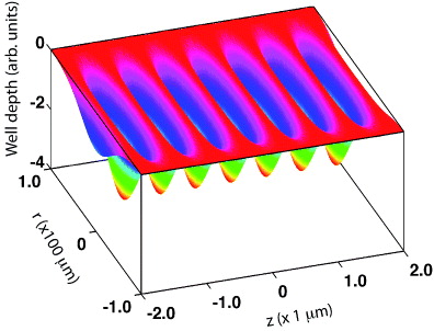
Figure 1. The intensity profile produced by two near counter-propagating fields that form an optical lattice for acceleration of o-Ps. A frequency difference between the two beams creates an optical lattice that uniformly accelerates particles that are trapped by the potential.
Download figure:
Standard imageThe optical lattice potential traps particles within the lattice sites when their energy is less than the well depth; a detailed treatment has been given previously for molecules [35, 36]. By changing the frequency difference between the two beams that create the lattice, a constant acceleration is produced by a linear frequency chirp (d(ω1 − ω2)/dt = β(t)) in one of the interfering beams. Initially, the overlapping fields are at the same frequency, trapping a group of particles whose velocity is centred at zero. For a moving source, such as a beam, the initial lattice velocity can be set to match it by initially having a frequency difference between the beams.
In the absence of collisions, the motion of a particle in the lattice in all three spatial dimensions is independent and therefore the force along each direction can be computed independently. As the gradient along the lattice direction is more than an order of magnitude greater than the radial direction, we can to a good approximation ignore the motion in the other directions providing the timescale of acceleration is fast compared to the oscillation period in the transverse radial direction [39].
To illustrate the essential physics of acceleration we consider motion along the lattice in 1D and assume that there is no radial gradient in the optical field. This approximation is justified for beams that are much larger than the initial spatial extent of the particles to be accelerated. Ignoring initial phase shifts between the two beams the 1D equation of motion in this case is given by

where  is the maximum force per unit mass supplied by the lattice, E0 is the electric field amplitude of the lattice beams and q is the lattice wavevector given by q = 4π/λ where λ is the wavelength of the lasers used to form the lattice. The rate of change of the frequency difference between the two lattice beams is given by the frequency chirp β(t). The velocity of the lattice potential due to the phase change introduced by the chirp is also the average velocity of the particles trapped and is given by

Although not derived here, the condition for a particle to be trapped and accelerated by the 1D moving lattice of equation (2) is given by [35],

This relation indicates that if the chirp is too high, and the lattice accelerates too quickly, the particles cannot be trapped by the moving potential. If the maximum force per unit mass or the lattice wavevector is too low, then the particles will also not be trapped and accelerated. In addition, if the particles are at the wrong phase, they will not be trapped and transported. This is best illustrated by plotting the velocity-position phase space of figure 2. Here particles that are initially in the closed red curves will be trapped and transported while the particles outside will not. These are repeated at each lattice site separated by approximately λ/2 as expected from figure 1. The maximum velocity of trapped particles for any position is shown as the central closed red curve in figure 2. This is given by ![$v(x) = \pm 2\sqrt {\beta /\psi }/q[\psi ^{-1}\cos (qx) -qx -\pi +\psi ^{-1}\sqrt {1 - \psi ^2} + \sin ^{-1}\psi ]^{1/2}$](https://content.cld.iop.org/journals/1367-2630/14/4/045005/revision1/nj416750ieqn4.gif) . The roots of this equation determine the spatial spread of the trapped particles for particular ψ,β and q. The first root has the analytical solution x1 = q−1(−π + sin−1ψ), while the second root, x2, must be determined numerically. The maximum velocity that a trapped particle can have occurs at the spatial location
. The roots of this equation determine the spatial spread of the trapped particles for particular ψ,β and q. The first root has the analytical solution x1 = q−1(−π + sin−1ψ), while the second root, x2, must be determined numerically. The maximum velocity that a trapped particle can have occurs at the spatial location  . The fraction, F, of particles that are initially in thermal equilibrium and can be trapped by the 1D lattice potential, can be calculated by the ratio of those in the trapping region and the total number as determined by the 1D velocity distribution function over one lattice site. This has been determined previously and is given by [36],
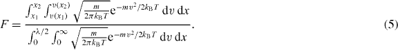
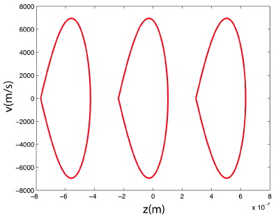
Figure 2. The shape of the periodic trapping regions in the position-velocity phase space of an accelerating optical lattice. Particles initially in the enclosed region will stay trapped during the constant acceleration provided by a linear chirp. The plots are calculated for Ps accelerated for ψ = 0.32 using a lattice beam intensity of 2 × 10¹⁰ W cm−2, chirp of β = 5 × 10²⁰ rad s−2, and central lattice wavelength of λ = 1064 nm.
Download figure:
Standard imageFigure 3 is a plot of the fraction accelerated as a function of ψ showing an almost linear decrease. These values represent the maximum for acceleration since for a realistic optical lattice, which has a radial variation in intensity, the fraction will vary in the radial direction due to the decrease in intensity from the axis of the lattice.
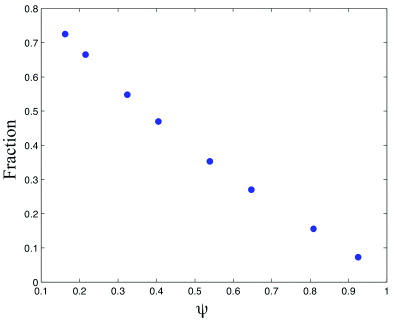
Figure 3. The fraction of particles accelerated as a function of ψ for a lattice beam intensity of 2 × 10¹⁰ W cm−2, chirp of β = 5 × 10²⁰ rad s−2, and central lattice wavelength of λ = 1064 nm. A temperature of 300 K was assumed for the positronium cloud.
Download figure:
Standard image4. Realistic parameters for the acceleration of ortho-positronium
While a range of laser parameters are suitable for acceleration of o-Ps, a maximum achievable velocity can be estimated by considering the intensity at which ionization becomes important on an acceleration timescale that is an order of magnitude less than the lifetime of o-Ps. An estimate for maximum intensities suitable for o-Ps acceleration can be determined from the work of Madsen and Lambropoulos [40, 41]. Thus, we limit our analysis to an intensity of 3.5 × 10¹¹ W cm−2 resulting in a multi-photon ionization probability of less than 10% for a 5 ns pulse duration. In addition, the ability to produce chirped pulses on timescales of a few nanoseconds is also technically feasible using the techniques developed for chirped pulse amplification [42]. Assuming a central laser wavelength of 1064 nm and a lattice produced by counter-propagating beams (q = 1.18 × 10⁷ m−1), the applied chirp from equation (4) cannot exceed 3.0 × 10²² rad s−2. The amplitude of the electric field for an intensity of 3.5 × 10¹¹ W cm−2 is E0 = 1.6 × 10⁹ Vm−1. For a 1 ns duration pulse this maximum chirp rate corresponds to a frequency excursion of less than 13.6 THz. Using equation (3), a stationary o-Ps bunch trapped in the optical lattice could be accelerated up to a velocity of 5.1 × 10³ km s−1 or equivalently a maximum energy of around 145 eV. For a 10 ns pulse with the same chirp rate, o-Ps could be accelerated up to a kinetic energy of 14.5 keV.
For a Gaussian laser beam focused to an e−2 radius of 60 μm, the approximate energy required for the 1 ns flat top pulse acceleration is 39.6 mJ, while for the 10 ns duration pulse an energy of 396 mJ is required. These pulse energies and durations are easily within reach of current table-top laser technology. The fraction of the o-Ps atoms that can be accelerated depends on a number of factors. The most important are the initial density, chirp rate, the volume of the lattice and the initial temperature of the gas. The lower the temperature of the o-Ps gas before acceleration, the more of the distribution can be captured and accelerated. Increasing the focused beam size from 60 to 600 μm, while keeping the same energies as above, reduces the lattice beam intensity to 3.5 × 10⁹ W cm−2. At this intensity, the 1 ns pulse can now accelerate particles up to a energy of 14.6 meV (51 km s−1) using a chirp rate of 3.0 × 10²⁰ rad s−1 and the 10 ns pulse up to a maximum energy of 1.46 eV with the same chirp rate. If we approximate the lattice region as a cylinder with a radius given by the spot size of the laser beams, two orders of magnitude more particles can be accelerated using a 600 μm radius lattice, when compared to the 60 μm case.
5. Numerical simulations
We now present numerical simulations of the acceleration of an o-Ps gas in a 1D lattice produced by realistic Gaussian laser beams with beam waist ω1,2 = 200 μm. As described above, samples of o-Ps can be produced using nanosecond wide pulsed positron beams on a routine basis in the laboratory. The o-Ps gas is considered to have zero mean velocity with a Gaussian spread in velocity and position.
The 1D velocity distribution in each direction has a full-width-half-maximum (FWHM) of  or an energy of 71 meV corresponding to an initial temperature of T = 300 K. We use a spatial Gaussian distribution with a FWHM of 200 μm. We consider acceleration in two regimes denoted as low and high intensity. The low intensity case corresponds to a single beam intensity of 2 × 10¹⁰ W cm−2 and frequency chirp of 5 × 10²⁰ rad s−2. The high intensity case uses an intensity of 3.5 × 10¹¹ W cm−2 and a chirp rate of 1.6 × 10²² rad s−2. In all simulations we use a super-Gaussian temporal intensity profile for each beam. This profile can be produced experimentally [43] and has a central region of constant intensity where the acceleration takes place. The lattice is uniformly accelerated utilizing a linear chirp in one of the lattice beams. To determine the final velocity distribution we solve equation (1) for up to 2000 non-interacting particles using a predictor–corrector method, which treats the forces in all three directions separately based on the both the o-Ps position and velocity.
Figure 4 shows plots of the velocity distribution produced by calculating the trajectories of particles in the lattice for the low intensity case with pulse durations of 1, 5 and 10 ns. The accelerated fraction in figure 4(a) (v = 85 km s−1) does not move beyond the initial width of the 1D velocity distribution function. At 5 ns (figure 4(b)), the accelerated distribution at v = 423 km s−1 has moved beyond the wings of the thermal distribution function. The accelerated bunch in figure 4(c) reaches a velocity of 847 km s−1 for the 10 ns duration pulse, in agreement with equation (3). Figure 5 shows the results of the simulations of the velocity distribution for the high intensity case (intensity of 3.5 × 10¹¹ W cm−2) with a chirp rate of 1.6 × 10²² rad s−2 for 1, 3 and 5 ns pulse durations. The much greater acceleration allowed by the higher intensity produces bunches of positronium atoms at velocities of around 2700 km s−1 and 13 600 km s−1 respectively for the 1 and 5 ns chirp cases. On the velocity scale used, the velocity distribution function is not resolved and is much narrower than indicated in the figure. The velocity spread gives values of Δv/v = 7 × 10⁻³ and 9 × 10⁻⁴ for the 1 and 5 ns pulses respectively.
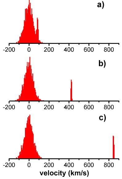
Figure 4. A simulation of 2000 o-Ps atoms accelerated in an optical lattice at a chirp rate of 5 × 10²⁰ rad s−2 and lattice beam intensity of 2 × 10¹⁰ W cm−2. (a) Acceleration for 1 ns, (b) 5 ns and (c) 10 ns.
Download figure:
Standard image
Figure 5. A simulation of 2000 o-Ps atoms accelerated for 1, 3 and 5 ns in an optical lattice at a chirp rate of 1.6 × 10²² rad s−2 and a lattice beam intensity of 3.5 × 10¹¹ W cm−2. The fraction of atoms accelerated is around 38% in each case.
Download figure:
Standard image6. Applications and concluding remarks
The collimated, energy variable, beam of positronium atoms produced by the method outlined herein could become a useful tool in atomic and fundamental physics. It should produce a larger flux on target than the current method of Ps beam creation, or the suggested route using Ps−, and the range of useable kinetic energies is much enhanced and does not have the same limitations as either technique. Thus, the field of positronium-gas scattering would benefit from a laser-accelerated positronium source.
Given the pulsed nature of the source, it will be possible to create beams of excited state positronium atoms by intersecting the ground state flux with appropriate laser beams. In particular, it can provide an efficient source of positronium in the 2S excited state, via two-photon Doppler free excitation. This state is metastable against radiative decay to the ground state, and its annihilation lifetime is enhanced over the ground state by a factor of 8 such that extended flight path experiments can be contemplated. These could include use of interferometric techniques to probe the gravitational interaction of positronium (see e.g. [44]), and tests of its charge neutrality, which has previously been proposed in the context of a positron storage ring scenario [45]. It may also be possible, now that cold antihydrogen can be held in a magnetic minimum trap [46, 47], to use an optical lattice to produce directed fluxes of the anti-atom for beam-type experiments, such as the proposed measurement of the ground state hyperfine splitting [48].
In conclusion, we have shown how travelling optical lattices can be used to produce collimated fluxes of o-Ps atoms on the nano-second time scale with a wide range of kinetic energies in the sub-keV region. The method can be applied using a suitably synchronised pulsed low energy positron source to form a cloud of o-Ps in vacuum. The resulting o-Ps kinetic energy can be chosen by varying the laser intensity, the pulse duration or the chirp rate of the lattice.
Acknowledgments
MC is grateful to the EPSRC for supporting his work in antimatter physics via the provision of a Senior Research Fellowship. We thank Dirk Peter van der Werf for help producing the final manuscript.