1. Introduction
Recently, due to climate change problems, the electrification of transport has received a lot of attention [
1,
2,
3]. Although electric propulsion for aircraft applications forms a very small portion of current standard aviation due to its limitations, this technology has the potential to be integrated into a wide range of future aircrafts. The distributed electric propulsion (DEP) concept considered in this paper is composed of several electrical motors to generate the required lift and thrust. Multiple propulsors are required because they generate less thrust than gas turbines, and therefore, the number of engine units should be increased [
2]. As the propulsors spin relatively slowly compared to jet engines, this can cause the noise level of the aircraft to be reduced [
4,
5]. In addition, as there are several engine units mounted on the wing, the safety of the aircraft improves due to motor redundancy. Moreover, distributing several motors along the wing might be helpful in alleviating the gust loads—actively or passively [
6]. Several research projects on distributed propulsion aircraft have been undertaken, however, there reamins room for further investigations [
7]. Leifsson et al. [
6] carried out a multidisciplinary design optimisation of a blended-wing–body transport aircraft with distributed propulsion. They showed that using distributed propulsion increased the lift-to-drag ratio of the wing. Patterson and German [
7] considered an initial conceptual aerodynamic design of a wing with several propulsors distributed along the wing span. It was concluded that lift improvement could be obtained by using leading edge propellers. Stoll et al. [
4] studied the effects of distributed electric propulsion on aircraft drag reduction. In their study, the leading edge asynchronous propellers technology (LEAPTech) concept was introduced with the objective of improving its aerodynamic efficiency. It was also shown that this concept resulted in drag reduction of up to 60%. NASA’s X-57 “Maxwell” was a flight demonstrator for DEP technology that consisted of several different configurations [
8]. In each configuration, one specific arrangement of distributed propulsors was considered. A comprehensive review of various distributed propulsion technologies and their potential applications for all-electric commercial aircraft was carried out by Gohardani et al. [
5].
In almost all of the proposed DEP concepts, the aircraft is equipped with high aspect ratio wings, and so the wing might undergo large deformations due to the high flexibility of the wing. Therefore, one of the main challenges of DEP configurations is the aeroelastic stability. Aeroelastic instabilities can result in the failure of structures, thus limiting their flight envelope. The detection of the conditions under which these instabilities appear is of primary importance for designers. When the wing is exposed to non-conservative forces, including aerodynamic forces, follower forces, and manoeuvre loads, the wing might enter the unstable zone at some specific conditions. The literature is very rich on the aeroelastic stability of the high aspect ratio wings ([
9,
10,
11,
12]), as is the effect of engines on the stability boundaries of aircraft wings ([
10,
13,
14,
15,
16]). Chang and Hodges [
9] studied the aeroelasticity and vibration of highly flexible aircraft using an exact beam formulation and unsteady aerodynamics. They investigated the effect of the flexible wing shape on the modal characteristics of the aircraft. The effect of the engine thrust and mass on the aeroelastic stability of the high aspect ratio wings was determined by Mardanpour et al. [
10]. It was shown that the engine’s location and mass have a significant effect on the stability of the flexible wing. This study was then continued by considering the effect of multiple engines on the aeroelastic trim and stability of flexible flying wings [
11]. Patil et al. [
12] studied the nonlinear aeroelasticity of flexible flying wings using a geometrically exact beam formulation. They showed that both structural and aerodynamic nonlinearities had direct effects on the aeroelastic behaviour of the wings. The effects of engine location, thrust and mass on the aeroelasticity of composite wings was considered by Amoozgar et al. [
14]. They showed that depending on the laminate ply angle, the engine thrust might have stabilising or destabilising effects. Mazidi and Fazelzadeh [
15] investigated the effect of wing sweep on the flutter speed of wings with and without the engine effects. It was concluded that wing sweep, engine thrust and mass affect the flutter speed and frequency of the wing.
None of the studies presented above considered the aeroelasticity of the electric aircraft wing with a DEP configuration using an exact formulation. Thus, in this study, the aeroelastic stability of a DEP aircraft wing was investigated and the effect of propulsors’ thrust and angular momentum on the stability of the wing was analysed. Hence, an exact beam formulation was combined with an unsteady aerodynamic model to capture the nonlinear aeroelasticity of the wing. The wing was equipped with several high-lift motors distributed equally along the span. Furthermore, one big propulsor was also attached to the tip of the wing to generate the required thrust for cruise flight.
In what follows, the problem is first defined in
Section 2 and then the aeroelastic governing differential equations are derived in
Section 3. Finally, in
Section 4, the obtained results are first verified against those available in the literature, and then the effect of the propulsors’ thrust, angular momentum and mass for two case studies on the aeroelastic stability of the wing are determined.
2. Problem Statement
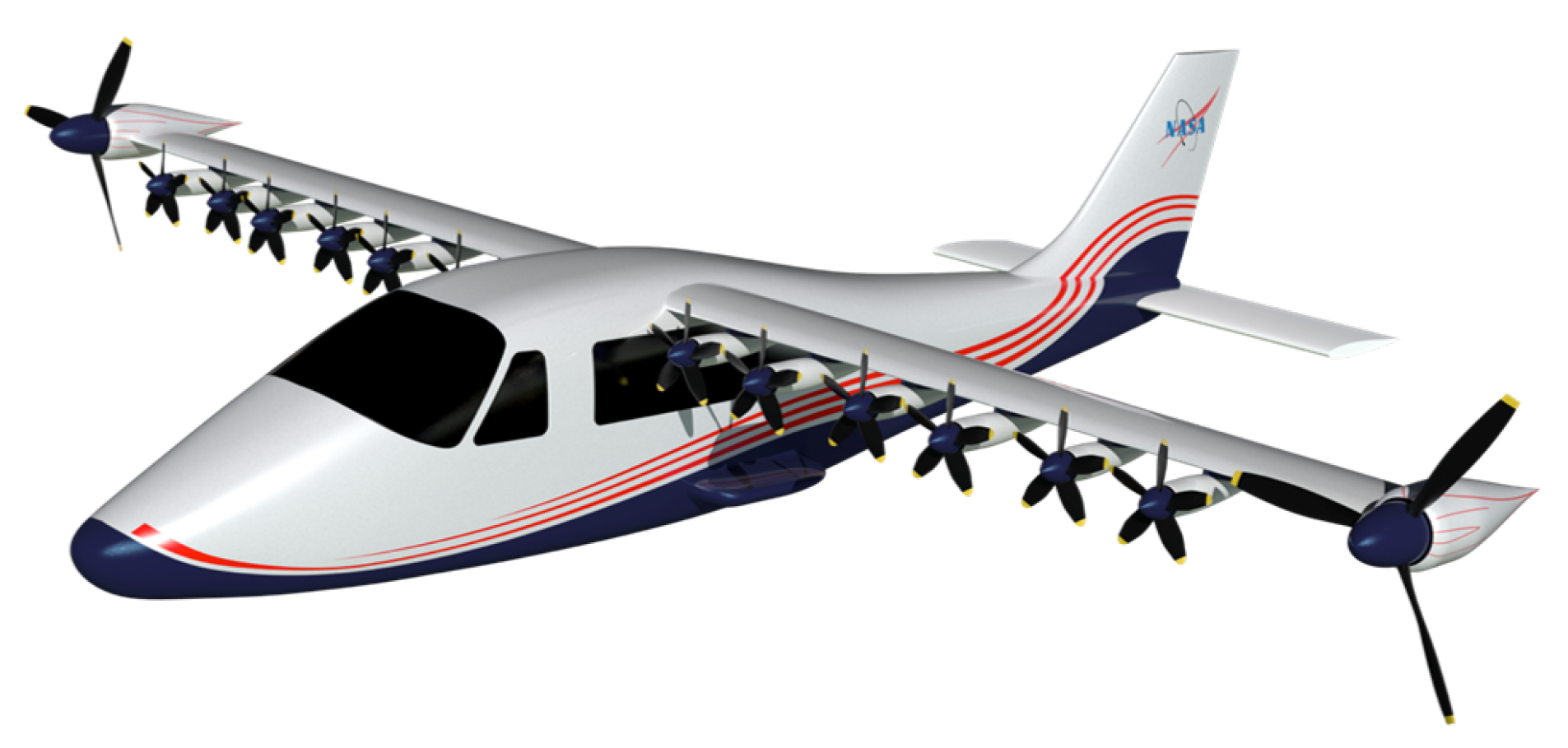
An aircraft wing with a distributed electric propulsion (DEP) configuration similar to the wing of the NASA’s X-57 “Maxwell” aircraft [
8] (
Figure 1) was considered. As shown in
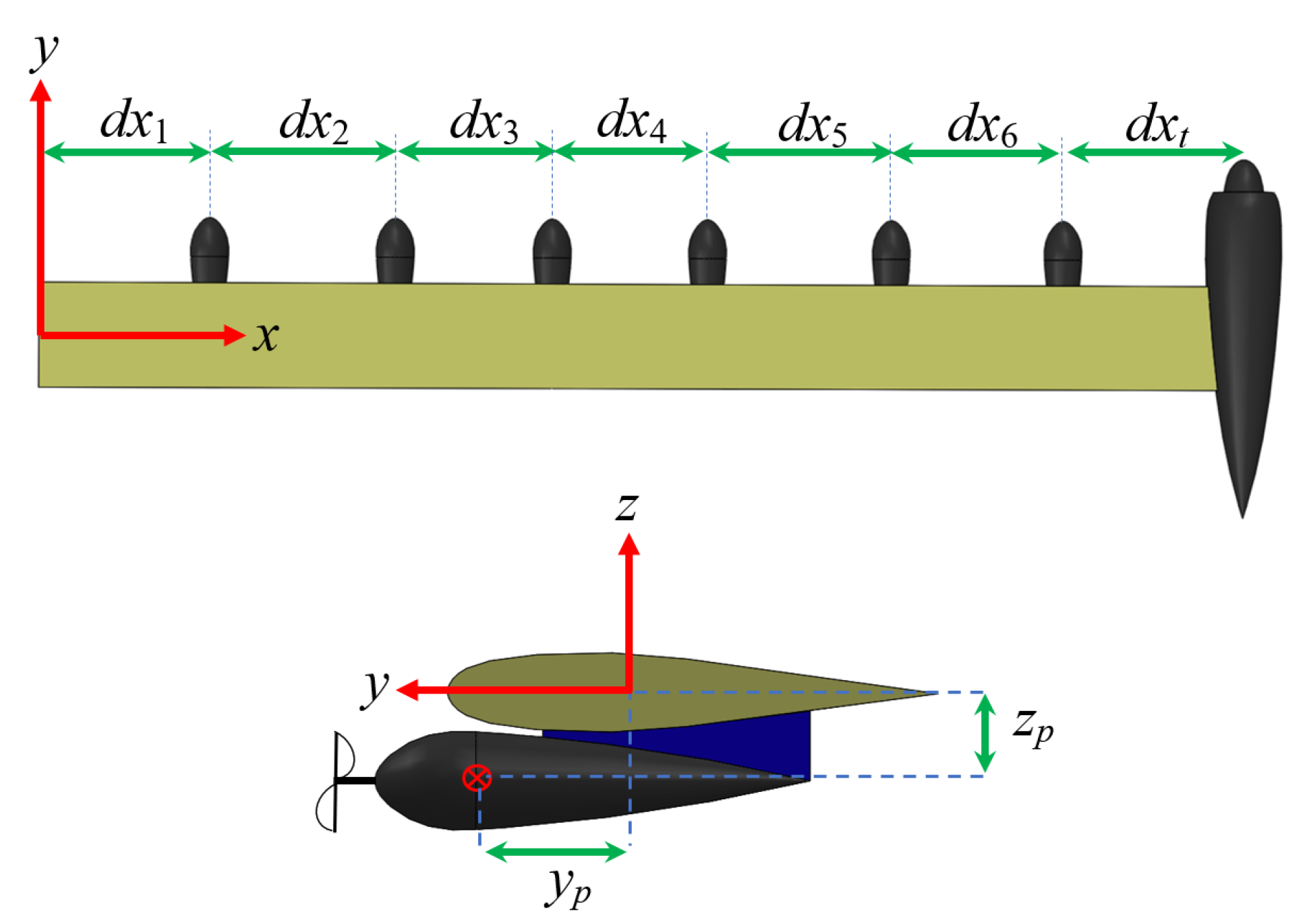
Figure 2, there are six high-lift motors and one tip propulsor all mounted on each semi-wing in different locations. The motors were distributed in the
x direction along the wing, and the position of the mass centre of each motor is denoted by
and
, in the
y and
z directions, respectively. The origin of the coordinate system is located at the root of the wing and on the wing elastic axis.
In this study, the masses of the electric motors were modelled as concentrated masses connected to the wing (through rigid attachments), and the equivalent thrust and angular momentum of the propellers were applied to the motor centre of mass. In the following, the aeroelastic equations were derived first and then the effects of the propulsors’ mass, thrust, and angular momentum on the aeroelasticity of the wing was investigated.
3. The Mathematical Model
The aeroelastic equations of the wing consist of the structural model and the aerodynamic model. The wing structure was modelled using the geometrically exact fully intrinsic beam equations [
17]. This beam formulation has been successfully used for a range of aerospace structures [
18,
19,
20,
21,
22]. The governing equations of the beam can be written as
where
and
are the internal forces and moments,
and
are the linear and angular velocities,
and
are the sectional linear and angular momenta, and
is the final curvature in which
which define the local axes at each point along the deformed reference axis.
and
are the strain measures which can be obtained using the cross-sectional properties as
contains the cross-sectional stiffness values of the wing. Furthermore, the linear and angular momenta can be obtained using the linear and angular velocities and the mass matrix as
where
is the mass per unit length of the wing, and
,
and
are the offsets of the wing mass centre from the reference axis in the
x,
y and
z directions, respectively. Furthermore,
,
,
and
are the cross-sectional moments of inertia of the wing.
The combined external forces and moments due to the aerodynamics (
) and the propulsors (
) are defined here by
and
and can be written as
It is noted that in the above equations, the propulsor loads (modelled using follower forces) are defined on the beam reference frame. Furthermore, the aerodynamic loads in the beam reference frame can be obtained from the aerodynamic loads in the aerodynamic reference frame (
,
) using the relations:
where
is the transformation matrix from the aerodynamic reference frame to the beam reference coordinate system,
defines the offsets between the aerodynamic centre and the beam reference, and (
) is the tilde operator converting a vector to a matrix. The unsteady aerodynamic loads in the aerodynamic coordinate system can be obtained using the intrinsic representation of Peters’ unsteady formulation ([
23,
24]) which can be written as
where
,
,
,
and
are the aerodynamic coefficients of the airfoil,
is the air density and
b is the wing semi-chord. Moreover,
,
and
are the air velocity measures and the total aerodynamic velocity,
, can be written as
It is noted that all aerodynamic coefficients mentioned above are zero except the lift coefficient, which is .
Furthermore,
is the inflow value which can be obtained as follows [
23]:
where
and
are the constant matrices/vectors defined in [
23].
The combined aeroelastic equations are discretized using a time–space scheme in which each parameter is defined on the left (
l), average (
a) and right (
r) in its spatial variation (
x), and start, mean and final in its temporal variation (
t) [
17]. In this study, the effect of propulsors’ mass, thrust and angular momentum were simulated through the nodal discretized equations (Equations (1)–(6)) given as [
19]
where
is the slope discontinuity, subscripts
refer to the nodal values on the left and right hand sides of each node, and superscript
is the node number. In addition,
and
are the external forces and moments due to both aerodynamic and propulsors’ thrust. Furthermore, the propulsors’ properties were introduced into the formulation through the nodal generalised momentum–velocity relations as
where
,
and
are the propulsor’s mass, moment of inertia, and location from the wing elastic axis, respectively,
is the propulsor’s angular momentum, and
is the identity matrix.
Finally, as the wing is clamped at the root, fixed boundary conditions are applied to close the formulation. To study the stability of the system, first the nonlinear steady state condition is determined by removing all time derivatives from the equations of motion and solving the resulting nonlinear static equations using the Newton–Raphson method. Then, the eigenvalues of the linearised system of the nonlinear steady-state conditions are calculated. If the real part of any eigenvalue is negative, this indicates that the system is unstable, and the dividing point between the stable and unstable behaviour is the flutter speed.
4. Verification and Results
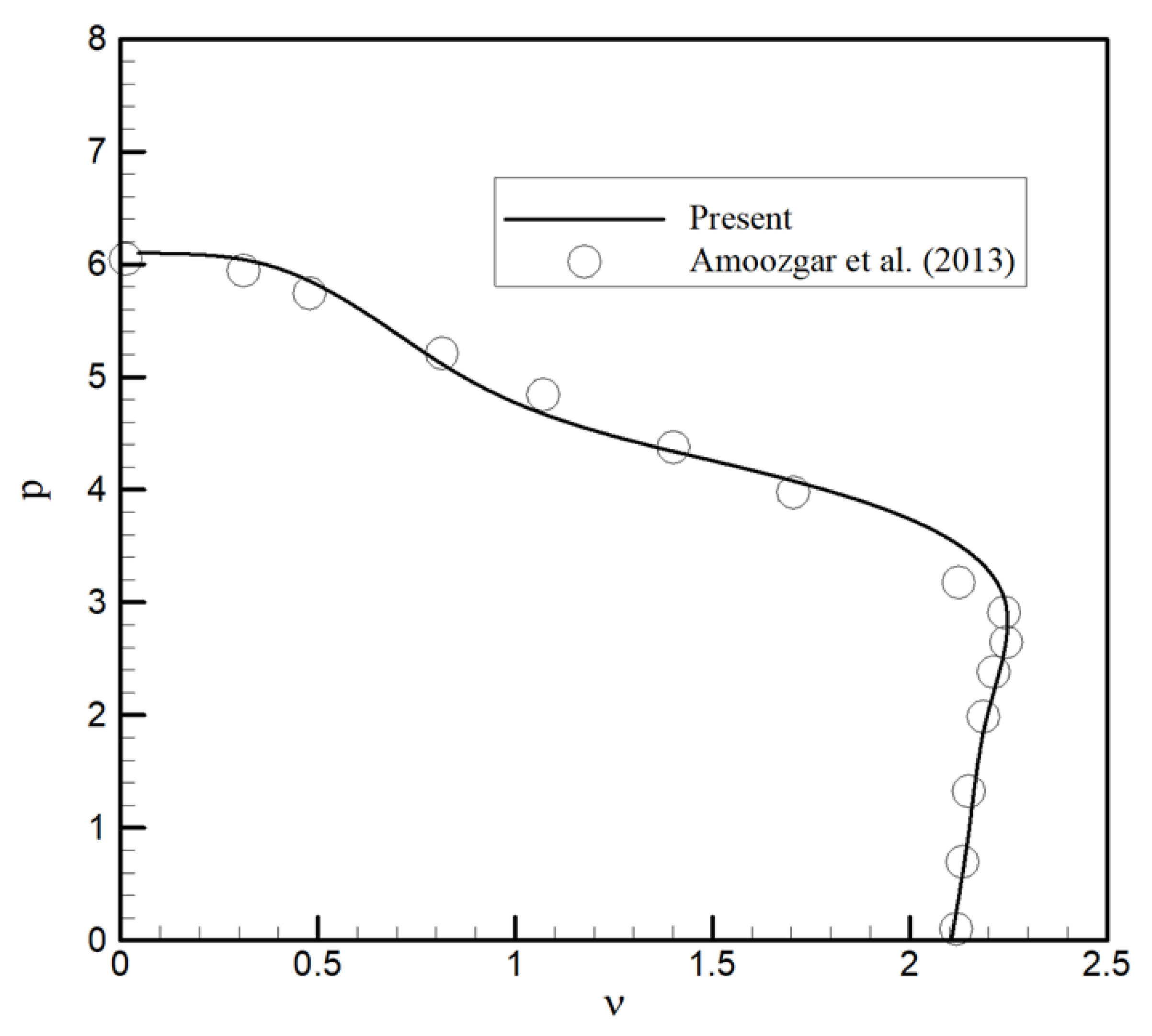
In order to verify the developed aeroelastic formulation, the flutter speed and frequency of a wing with an attached engine (at the tip of the wing) is determined and compared with those reported by Amoozgar et al. [
14].
Figure 3 shows that the results are in good agreement, which verifies the accuracy of the developed aeroelastic code. In this case, the engine is located at the tip of the wing, and the wing is subjected to both aerodynamic loads and engine thrust. Here,
is the nondimensional flutter speed,
p is the nondimensional engine thrust, and
is the stiffness ratio defined as
where
and
are the out-of-plane bending stiffness and torsional stiffness of the wing, respectively. A wing similar to the configuration shown in
Figure 1, representing the wing of the X-57 aircraft with several motors, was considered next. The wing properties were presented in
Table 1 ([
24]). It must be noted here that the propulsors’ properties were generated as an estimation of the X-57 aircraft. There were 6 high-lift motors distributed along the span of the wing, and one cruise propulsor located at the tip of the wing.
First, the flutter speed and frequency of the wing were compared with those of the clean wing (without any propulsors) and reported in
Table 2. In this case, it was assumed that the thrust of each high-lift engine was
N and the thrust of the cruise propulsor was
N. It was noted that here the angular momentum of these propulsors was assumed to be zero (e.g.,
). This combination of motors resulted in an improvement of the flutter speed with respect to the clean wing.
Two cases were considered next, which represented two flight conditions of the wing. In the first case, all of the high-lift motors were assumed to be switched off and only the cruise propulsor was switched on. In the second case, the tip propulsor was off and the high-lift motors were on. The flutter speed and frequency of the wing for these two cases were determined and compared with the case when all the motors were switched off, and reported in
Table 3. Although the mass and thrust of the propulsors affect the flutter speed of the wing, the relative difference between the cases was smaller than 2% and no variation in the flutter frequency was visible.
Then, the effect of the propulsor’s angular momentum (
) on the flutter speed and frequency of the wing for the two prescribed cases were determined using Equation (
24). It is assumed here that all motors are positioned exactly on the elastic axis of the wing, and therefore
—however, they have vertical offsets from the elastic axis (e.g.,
).
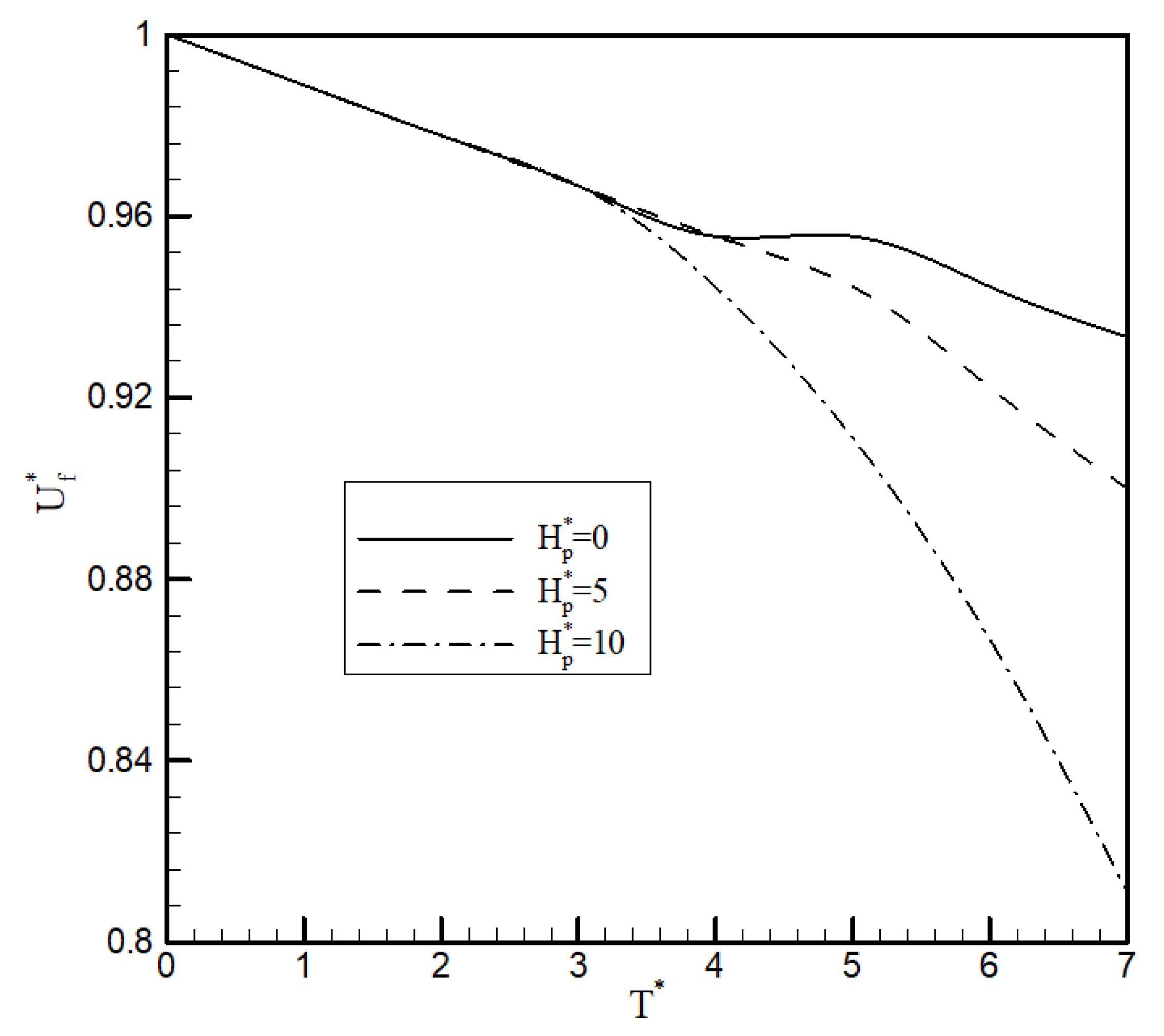
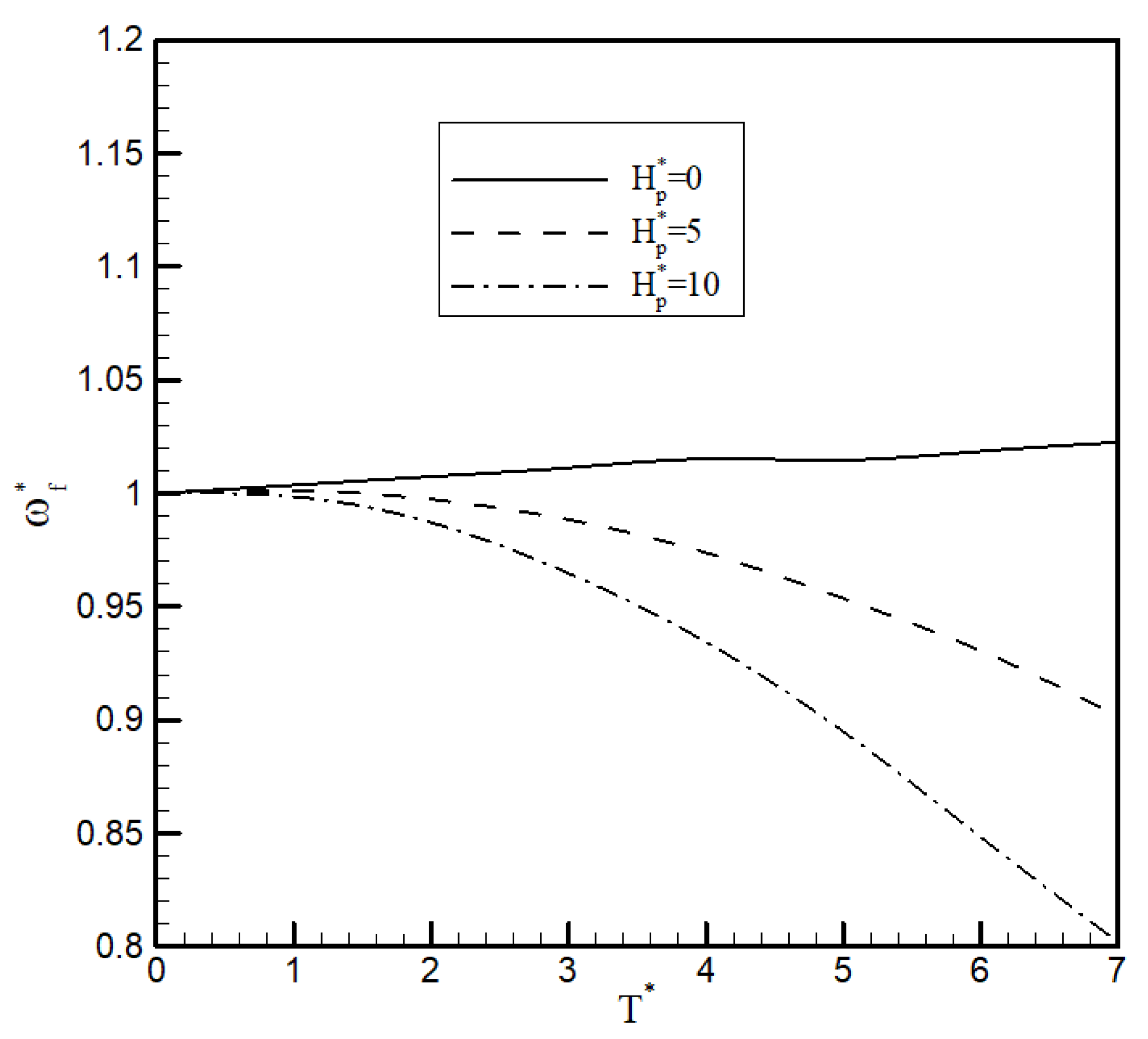
Figure 4 and
Figure 5 show the effect of tip propulsor’s thrust (
) and angular momentum (
) on the flutter speed and flutter frequency of the wing, respectively. The propulsor vertical offset from the elastic axis is
where
c is the chord length of the wing. The flutter speed, propulsor thrust and angular momentum were nondimensionalised with respect to the flutter speed of the clean wing, the nominal thrust and the nominal angular momentum of the propulsor, respectively. This shows that the angular momentum of the tip propulsor did not affect the flutter speed of the wing for small values of thrust; however, for higher values of thrust, it reduced the flutter speed. Also, as the angular momentum increases, the flutter speed decreases.
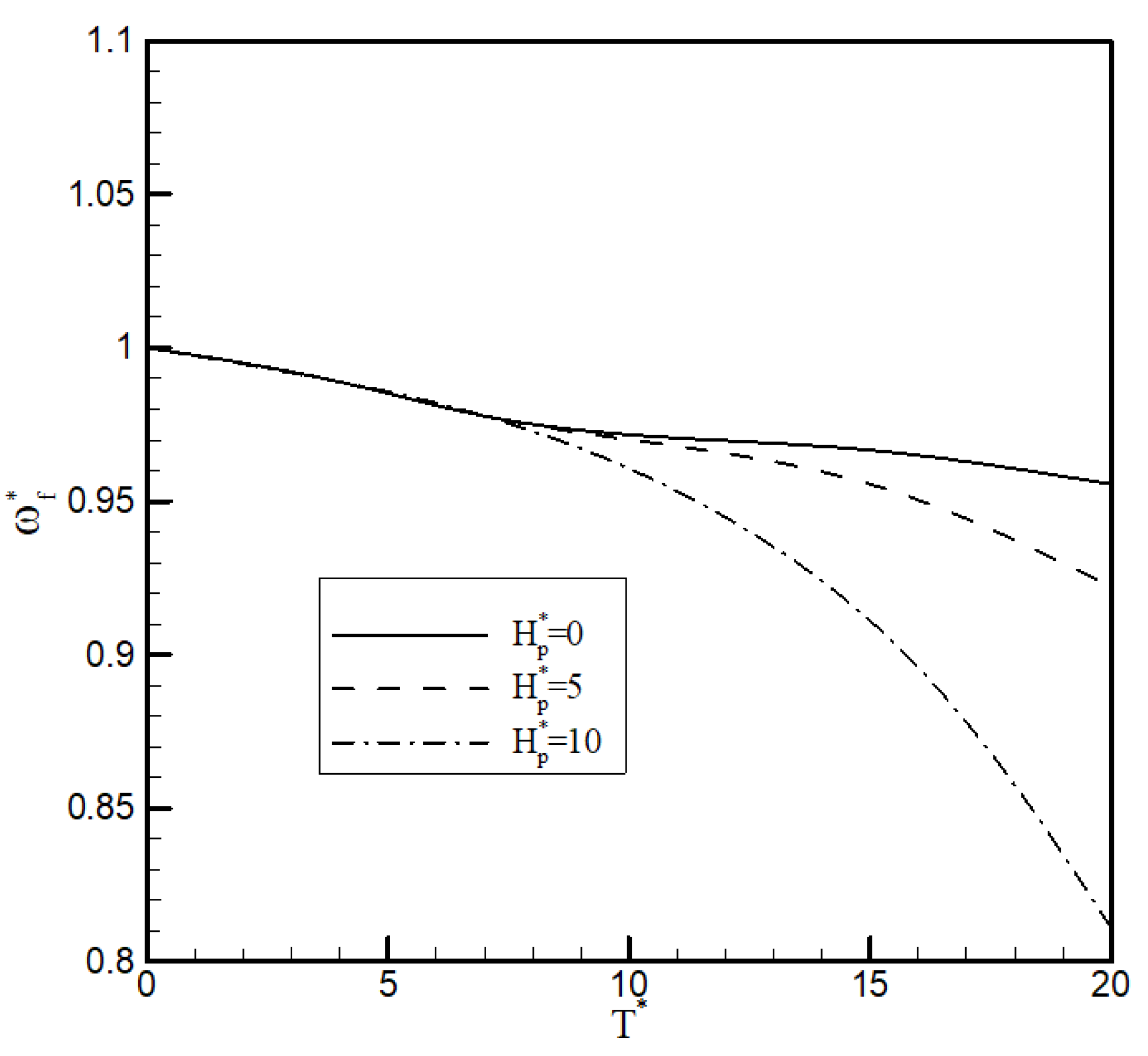
Furthermore, the engine angular momentum affects the flutter frequency of the wing, as shown in
Figure 5. By increasing the propulsor’s angular momentum, the flutter frequency decreases with an increase in thrust. This highlights that the coupling between the wing deformations and the propulsor’s angular momentum could affect the aeroelastic behaviour of the system, especially at high thrust values, and it should be considered for aircraft using DEP configurations.
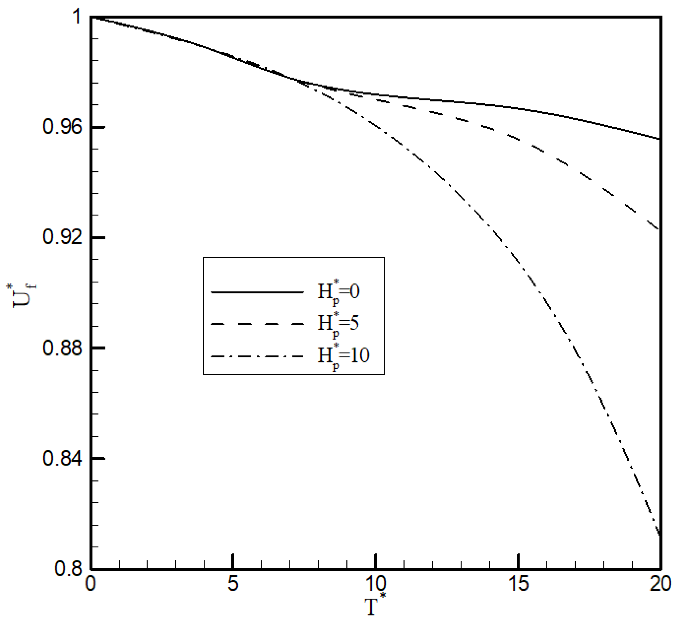
Then, the aeroelastic stability of the second case (case 2) was determined. In this case, the high-lift motors were on, but the tip propulsor was off. The angular momentum was nondimensionalised with respect to the nominal angular momentum of the high-lift motors. In addition, it was assumed that all motors had the same offset value as the propulsor’s offset from the elastic axis (
). In this case, as shown in
Figure 6 and
Figure 7, the angular momentum of the motors affects the flutter speed and frequency of the wing, but only for very high values of thrust. This highlighted that the tip propulsor had more impact on the stability of the wing than the high-lift motors.
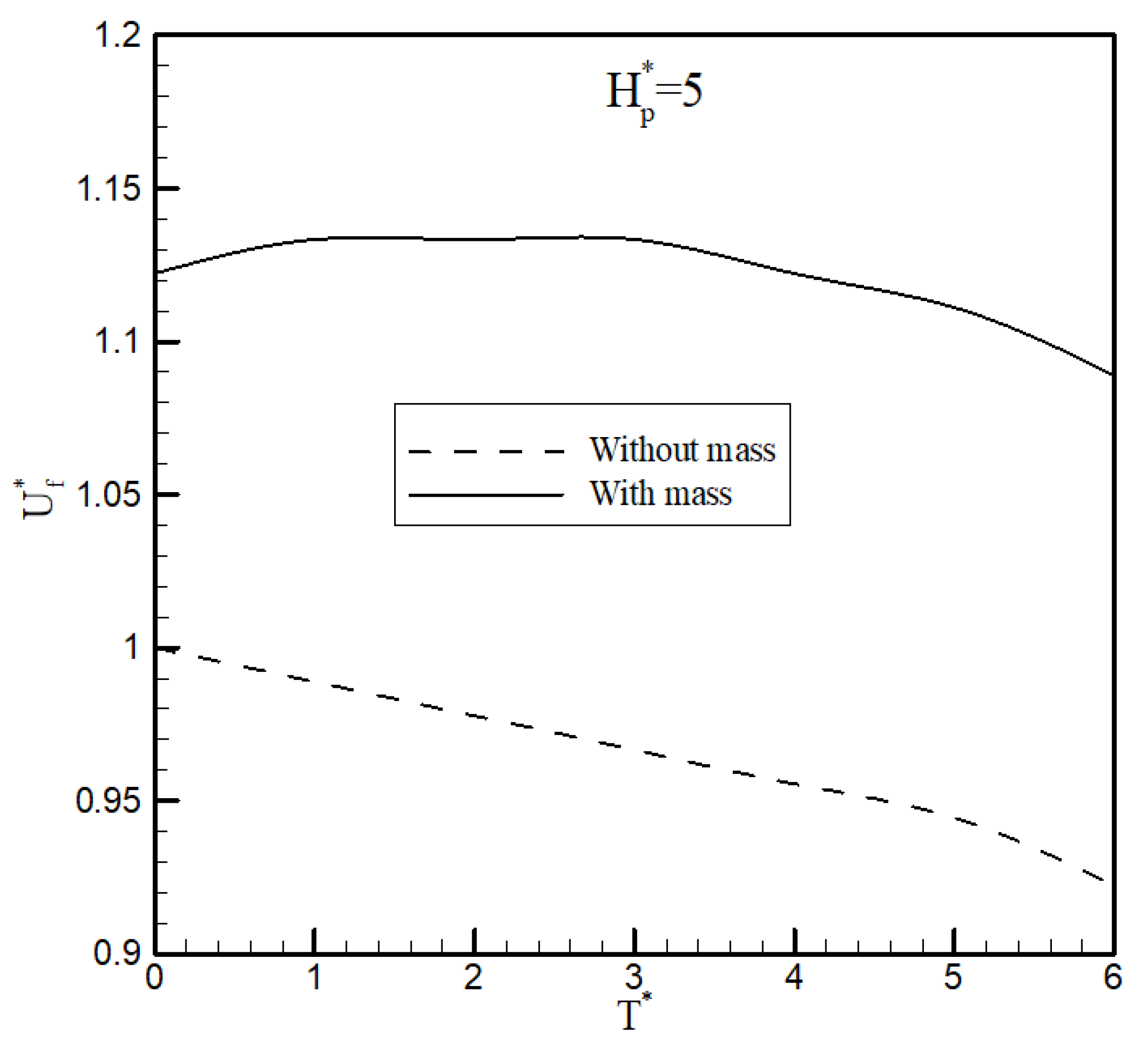
In both cases considered above, the effects of the mass of the high-lift motors and tip propulsor were neglected. Now, the effects of the mass of all propulsors combined with the other parameters are considered.
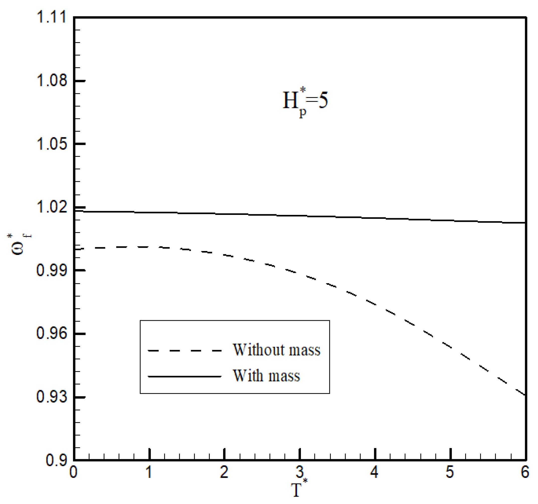
Figure 8 and
Figure 9 show the effect of the mass of all engines on the flutter speed of the wing for case 1 when the angular momentum of the tip propulsor is
. First, when the mass of all engines is added to the simulation, the flutter speed increases. In addition, in this case, by increasing the thrust of the propulsor, the flutter speed changes, but the rate of change is smaller than for the case when the mass was not considered. This also applies to the flutter frequency, as shown in
Figure 9. When the mass of all engines was considered, the flutter frequency did not change significantly. This shows that the mass of the tip propulsor had a stabilising effect on the aeroelasticity of the wing.


 ,
, 


