Double Linker Triphenylamine Dyes for Dye-Sensitized Solar Cells

 , , , , and
Abstract
:
1. Introduction
2. Materials and Methods
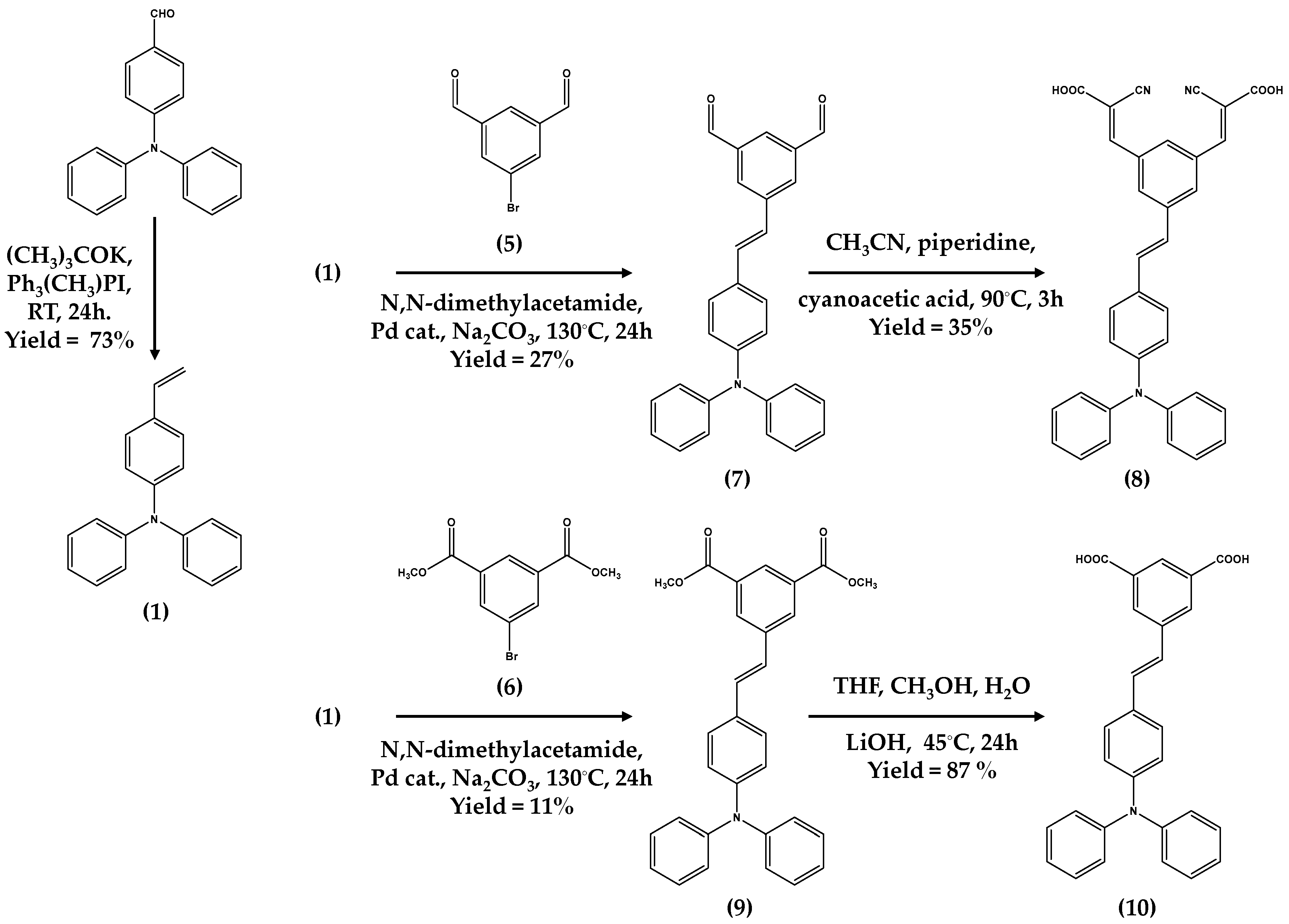
2.1. Dye Synthesis
2.1.1. Synthesis of (2Z, 2′Z)-3, 3′-(5-((E)-4-(diphenylamino) styryl)-1, 3-phenylene) bis (2-cyanoacrylic acid) (8)
2.1.2. Synthesis of 5-[2-(4-Diphenylamino-phenyl)-vinyl]-isophthalic Acid (10)
2.2. Device Making and Testing
2.3. Atomistic Modelling Simulations
3. Results and Discussion
3.1. Dye Synthesis
3.2. Device Performance
3.2.1. Experimental
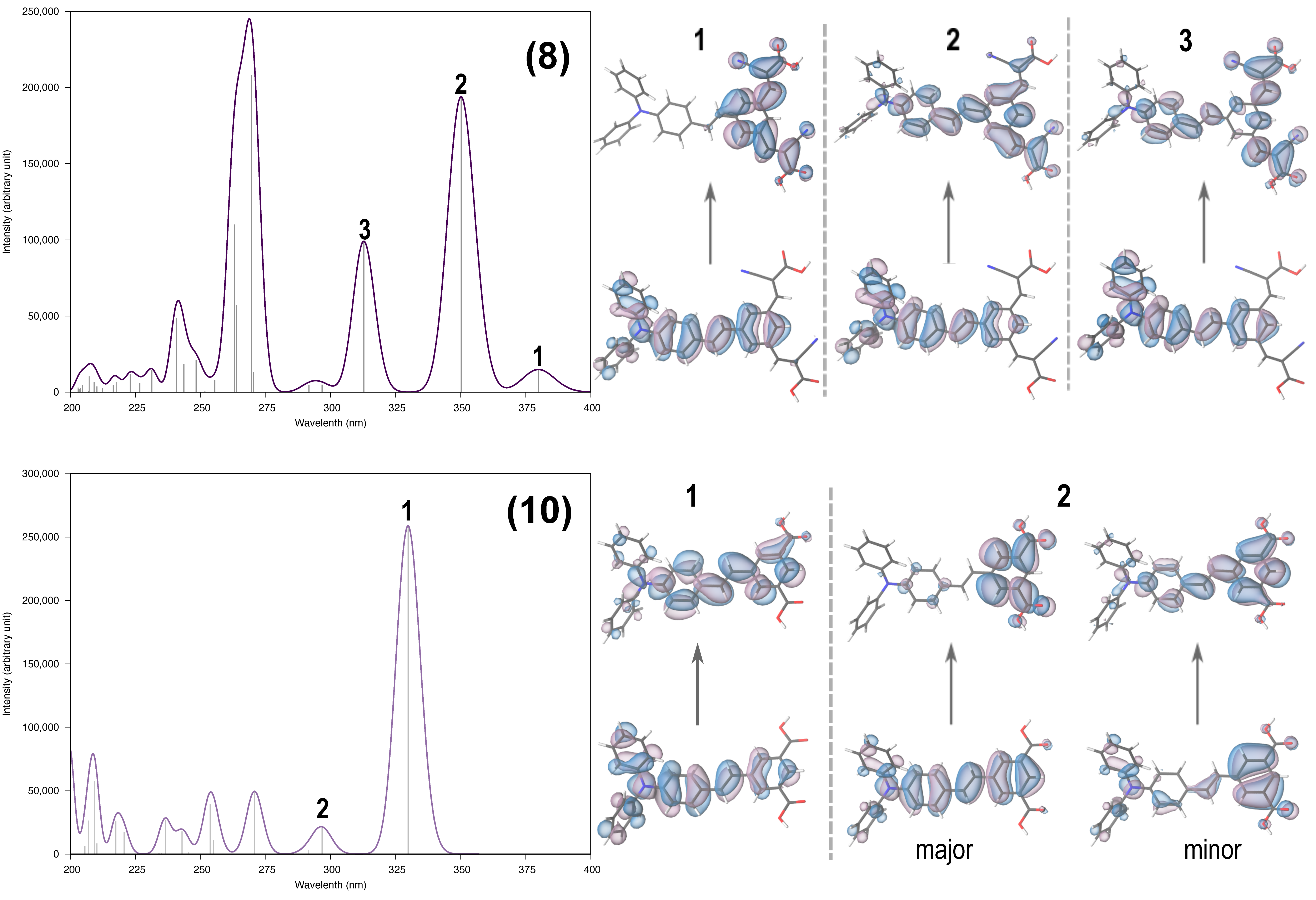
3.2.2. Simulation of the Dye Gas-Phase Spectra
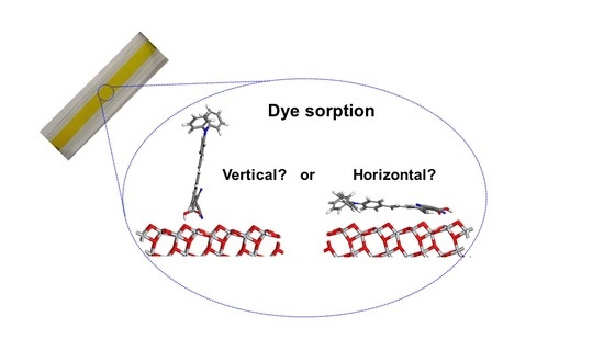
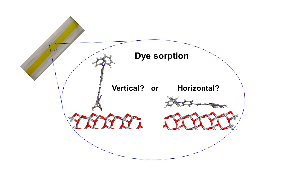
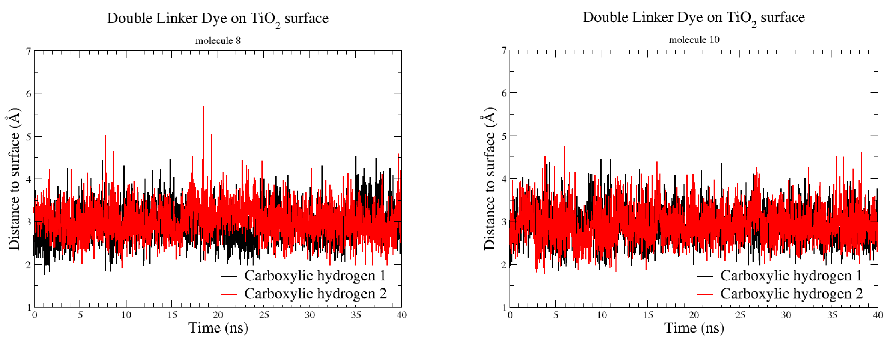
3.3. Bonding Interactions between the Dye and TiO2 Surface—Atomistic Modelling
4. Conclusions
Supplementary Materials
Author Contributions
Funding
Computing Resources
Conflicts of Interest
References
- O’Regan, B.; Grätzel, M. A low-cost, high-efficiency solar cell based on dye-sensitized colloidal TiO2 films. Nature 1991, 353, 737–740. [Google Scholar] [CrossRef]
- Nazeeruddin, M.K.; De Angelis, F.; Fantacci, S.; Selloni, A.; Viscardi, G.; Liska, P.; Ito, S.; Takeru, B.; Grätzel, M. Combined Experimental and DFT-TDDFT Computational Study of Photoelectrochemical Cell Ruthenium Sensitizers. J. Am. Chem. Soc. 2005, 127, 16835–16847. [Google Scholar] [CrossRef] [PubMed]
- Cao, Y.; Bai, Y.; Yu, Q.; Cheng, Y.; Liu, S.; Shi, D.; Gao, F.; Wang, P. Dye-Sensitized Solar Cells with a High Absorptivity Ruthenium Sensitizer Featuring a 2-(Hexylthio)thiophene Conjugated Bipyridine. J. Phys. Chem. C 2009, 113, 6290–6297. [Google Scholar] [CrossRef]
- Nazeeruddin, M.K.; Péchy, P.; Grätzel, M. Efficient panchromatic sensitization of nanocrystalline TiO2 films by a black dye based on a trithiocyanato–ruthenium complex. Chem. Commun. 1997, 1, 1705–1706. [Google Scholar] [CrossRef]
- Sun, Y.; Onicha, A.C.; Myahkostupov, M.; Castellano, F.N. Viable Alternative to N719 for Dye-Sensitized Solar Cells. ACS Appl. Mater. Interfaces 2010, 2, 2039–2045. [Google Scholar] [CrossRef]
- Shiau, S.-Y.; Chang, C.-H.; Chen, W.-J.; Wang, H.-J.; Jeng, R.-J.; Lee, R.-H. Star-shaped organic semiconductors with planar triazine core and diketopyrrolopyrrole branches for solution-processed small-molecule organic solar cells. Dyes Pigments 2015, 115, 35–49. [Google Scholar] [CrossRef]
- Yen, Y.-S.; Chou, H.-H.; Chen, Y.-C.; Hsu, C.-Y.; Lin, J.T. Recent developments in molecule-based organic materials for dye-sensitized solar cells. J. Mater. Chem. 2012, 22, 8734–8747. [Google Scholar] [CrossRef]
- Chen, Y.-C.; Lin, J.T. Multi-anchored sensitizers for dye-sensitized solar cells. Sustain. Energy Fuels 2017, 1, 969–985. [Google Scholar] [CrossRef]
- Abdalhadi, S.M.; Connell, A.; Zhang, X.; Wiles, A.A.; Davies, M.L.; Holliman, P.J.; Cooke, G. Convenient synthesis of EDOT-based dyes by CH-activation and their application as dyes in dye-sensitized solar cells. J. Mater. Chem. A 2016, 4, 15655–15661. [Google Scholar] [CrossRef] [Green Version]
- Connell, A.; Holliman, P.J.; Davies, M.L.; Gwenin, C.D.; Weiss, S.; Pitak, M.B.; Horton, P.N.; Coles, S.J.; Cooke, G. A Study of Dye Anchoring Points in Half-squarylium Dyes for Dye-Sensitized Solar Cells. J. Mater. Chem. A 2014, 2, 4055–4066. [Google Scholar] [CrossRef] [Green Version]
- Connell, A.; Holliman, P.J.; Jones, E.W.; Furnell, L.; Kershaw, C.; Davies, M.L.; Gwenin, C.D.; Pitak, M.B.; Coles, S.J.; Cooke, G. Multiple linker Half-squarylium Dyes for Dye-Sensitized Solar Cells; Are Two Linkers Better than One? J. Mater. Chem. A 2015, 3, 2883–2894. [Google Scholar] [CrossRef] [Green Version]
- Holliman, P.J.; Kershaw, C.P.; Jones, E.W.; McGettrick, J.; Geatches, D.; Metz, S.; Sen, K.; Tizzard, G.J.; Coles, S.J. Novel Benzothiazole Half-Squaraines: Model Chromophores to Study Dye-TiO2 Interactions in Dye-Sensitized Solar Cells. J. Mater. Chem. A. 2020. paper under review. [Google Scholar]
- Yao, Z.; Zhang, M.; Li, R.; Yang, L.; Qiao, Y.; Wang, P. A Metal-Free N-Annulated Thienocyclopentaperylene Dye: Power Conversion Efficiency of 12% for Dye-Sensitized Solar Cells. Angew. Chem. Int. Ed. 2015, 54, 5994–5998. [Google Scholar] [CrossRef]
- Yao, Z.; Zhang, M.; Wu, H.; Yang, L.; Li, R.; Wang, P. Donor/Acceptor Indenoperylene Dye for Highly Efficient Organic Dye-Sensitized Solar Cells. J. Am. Chem. Soc. 2015, 137, 3799–3802. [Google Scholar] [CrossRef]
- Yella, A.; Mai, C.-L.; Zakeeruddin, S.M.; Chang, S.-N.; Hsieh, C.-H.; Yeh, C.-Y.; Grätzel, M. Molecular engineering of push-pull porphyrin dyes for highly efficient dye-sensitized solar cells: The role of benzene spacers. Angew. Chem. Int. Ed. 2014, 53, 2973–2977. [Google Scholar] [CrossRef] [PubMed]
- Kakiage, K.; Aoyama, Y.; Yano, T.; Oya, K.; Kyomen, T.; Hanaya, M. Fabrication of a high-performance dye-sensitized solar cell with 12.8% conversion efficiency using organic silyl-anchor dyes. Chem. Commun. 2015, 51, 6315–6317. [Google Scholar] [CrossRef]
- Kakiage, K.; Aoyama, Y.; Yano, T.; Oya, K.; Fujisawa, J.; Hanaya, M. Highly-efficient dye-sensitized solar cells with collaborative sensitization by silyl-anchor and carboxy-anchor dyes. Chem. Commun. 2015, 51, 15894–15897. [Google Scholar] [CrossRef]
- Zhang, F.; Luo, Y.-H.; Song, J.-S.; Guo, X.-Z.; Liu, W.-L.; Maa, C.-P.; Huang, Y.; Ge, M.-F.; Bo, Z.; Meng, Q.-B. Triphenylamine-based dyes for dye-sensitized solar cells. Dyes Pigments 2009, 81, 224–230. [Google Scholar] [CrossRef]
- Holliman, P.J.; Mohsen, M.; Connell, A.; Davies, M.L.; Al-Salihi, K.; Pitak, M.B.; Tizzard, G.J.; Coles, S.J.; Harrington, R.W.; Clegg, W.; et al. Ultra-fast Co-Sensitization and Tri-Sensitization of Dye-Sensitized Solar Cells with N719, SQ1 and Triarylamine Dyes. J. Mater. Chem. 2012, 22, 13318–13327. [Google Scholar] [CrossRef]
- Hao, Y.; Tian, H.; Cong, J.; Yang, W.; Bora, I.; Sun, L.; Boschloo, G.; Hagfeldt, A. Triphenylamine Groups Improve Blocking Behaviour of Phenoxazine Dyes in Cobalt-Electrolyte-Based Dye-Sensitized Solar Cells. ChemPhysChem 2014, 15, 3476–3483. [Google Scholar] [CrossRef]
- Wan, Z.; Jia, C.; Wang, Y.; Yao, X. Dithiafulvenyl–triphenylamine organic dyes with alkyl chains for efficient coadsorbent-free dye sensitized solar cells. RSC Adv. 2015, 5, 50813–50820. [Google Scholar] [CrossRef]
- Chen, S.; Pei, J.; Pang, Z.; Wu, W.; Yu, X.; Zhang, C. Axial-symmetric conjugated group promoting intramolecular charge transfer performances of triphenylamine sensitizers for dye-sensitized solar cells. Dyes Pigments 2020, 174, 108029–108038. [Google Scholar] [CrossRef]
- Ferdowsi, P.; Saygili, Y.; Jazaeri, F.; Edvinsson, T.; Mokhtari, J.; Zakeeruddin, S.M.; Liu, Y.; Grätzel, M.; Hagfeldt, A. Molecular Engineering of Simple Metal-Free Organic Dyes Derived from Triphenylamine for Dye-Sensitized Solar Cell Applications. ChemPhysChem 2020, 13, 212–220. [Google Scholar] [CrossRef] [PubMed] [Green Version]
- Wu, Z.-S.; Song, X.-C.; Liu, Y.-D.; Zhang, J.; Wang, H.-S.; Chen, Z.-J.; Liu, S.; Weng, Q.; An, Z.-W.; Guo, W.-J. New organic dyes with varied arylamine donors as effective co-sensitizers for ruthenium complex N719 in dye sensitized solar cells. J. Power Sources 2020, 451, 227776–227785. [Google Scholar] [CrossRef]
- Clifford, J.N.; Palomares, E.; Nazeeruddin, M.K.; Thampi, R.; Grätzel, M.; Durrant, J.R. Multistep Electron Transfer Processes on Dye Co-sensitized Nanocrystalline TiO2 Films. J. Am. Chem. Soc. 2004, 126, 5670–5761. [Google Scholar] [CrossRef]
- Choi, H.; Kim, S.; Kang, S.O.; Ko, J.; Kang, M.-S.; Clifford, J.N.; Forneli, A.; Palomares, E.; Nazeeruddin, M.K.; Grätzel, M. Stepwise Cosensitization of Nanocrystalline TiO2 Films Utilizing Al2O3 Layers in Dye-Sensitized Solar Cells. Angew. Chem. Int. Ed. 2008, 47, 8259–8263. [Google Scholar] [CrossRef]
- Clifford, J.N.; Forneli, A.; Chen, H.; Torres, T.; Tan, S.; Palomares, E. Co-sensitized DSCs: Dye selection criteria for optimized device Voc and efficiency. J. Mater. Chem. 2011, 21, 1693–1696. [Google Scholar] [CrossRef]
- Lan, C.-M.; Wu, H.-P.; Pan, T.-Y.; Chang, C.-W.; Chao, W.-S.; Chen, C.-T.; Wang, C.-L.; Lin, C.-Y.; Diau, E.W.-G. Enhanced photovoltaic performance with co-sensitization of porphyrin and an organic dye in dye-sensitized solar cells. Energy Environ. Sci. 2012, 5, 6460–6464. [Google Scholar] [CrossRef]
- Yella, A.; Lee, H.-W.; Tsao, H.N.; Yi, C.; Chandiran, A.K.; Nazeeruddin, M.K.; Diau, E.W.-G.; Yeh, C.-Y.; Zakeeruddin, S.M.; Grätzel, M. Porphyrin-Sensitized Solar Cells with Cobalt (II/III)–Based Redox Electrolyte Exceed 12 Percent Efficiency. Science 2011, 334, 629–634. [Google Scholar] [CrossRef]
- Holliman, P.J.; Davies, M.L.; Connell, A.; Vaca Velasco, B.; Watson, T.M. Ultra-fast dye sensitisation and co-sensitisation for dye sensitized solar cells. Chem. Commun. 2010, 46, 7256–7258. [Google Scholar] [CrossRef]
- Davies, M.L.; Watson, T.; Holliman, P.J.; Connell, A.; Worsley, D. In situ monitoring of room temperature ultra-fast sensitization for dye sensitized solar cells. Chem. Commun. 2014, 50, 12512–12514. [Google Scholar] [CrossRef] [PubMed] [Green Version]
- Holliman, P.J.; Al-Salihi, K.J.; Connell, A.; Davies, M.L.; Jones, E.W.; Worsley, D.A. Development of Selective, Ultra-fast Multiple Co-sensitization to Control Dye Loading in Dye-Sensitized Solar Cells. RSC Adv. 2014, 4, 2515–2522. [Google Scholar] [CrossRef] [Green Version]
- Wu, G.; Kong, F.; Zhang, Y.; Zhang, X.; Li, J.; Chen, W.; Zhang, C.; Dai, S. Effect of different acceptors in di-anchoring triphenylamine dyes on the performance of dye-sensitized solar cells. Dyes Pigments 2014, 105, 1–6. [Google Scholar] [CrossRef]
- Sen, A.; Groβ, A. Does Involving Additional Linker Always Increase the Efficiency of an Organic Dye for p-Type Dye-Sensitized Solar Cells? ACS Appl. Energy Mater. 2019, 2, 6341–6347. [Google Scholar] [CrossRef]
- Wang, Q.; Moser, J.-E.; Grätzel, M. Electrochemical Impedance Spectroscopic Analysis of Dye-Sensitized Solar Cells. J. Phys. Chem. B 2005, 109, 14945–14953. [Google Scholar] [CrossRef] [PubMed] [Green Version]
- Han, J.; Fan, F.; Xu, C.; Lin, S.; Wei, M.; Duan, X.; Wang, Z.L. ZnO nanotube-based dye-sensitized solar cell and its application in self-powered Devices. Nanotechnology 2010, 21, 405203. [Google Scholar] [CrossRef]
- Vaghasiya, J.V.; Sonigara, K.K.; Soni, S.S.; Tan, S.C. Dual Functional Hetero-anthracene Based Single Component Organic Ionic Conductors as Redox Mediator cum Light Harvester for Solid State Photoelectrochemical Cells. J. Mater. Chem. A 2018, 6, 4868–4877. [Google Scholar] [CrossRef]
- Chal, P.; Shit, A.; Nandi, A.K. Dye-Sensitized Solar Cell from a New Organic n-Type Semiconductor/Polyaniline Composite: Insight from Impedance Spectroscopy. J. Mater. Chem. C 2016, 4, 272–285. [Google Scholar] [CrossRef]
- Li, J.-Y.; Chen, C.-Y.; Lee, C.-P.; Chen, S.-C.; Lin, T.-H.; Tsai, H.-H.; Ho, K.-C.; Wu, C.-G. Unsymmetrical Squaraines Incorporating the Thiophene Unit for Panchromatic Dye-Sensitized. Sol. Cells Org. Lett. 2010, 12, 5454–5457. [Google Scholar] [CrossRef]
- Hagberg, D.P.; Marinado, T.; Karlsson, K.M.; Nonomura, K.; Qin, P.; Boschloo, G.; Brinck, T.; Hagfeldt, A.; Sun, L. Tuning the HOMO and LUMO Energy Levels of Organic Chromophores for Dye Sensitized Solar Cells. J. Org. Chem. 2007, 72, 9550–9556. [Google Scholar] [CrossRef]
- Yum, J.-H.; Walter, P.; Huber, S.; Rentsch, D.; Geiger, T.; Nüesch, F.; De Angelis, F.; Grätzel, M.; Nazeeruddin, M.K. Efficient Far Red Sensitization of Nanocrystalline TiO2 Films by an Unsymmetrical Squaraine Dye. J. Am. Chem. Soc. 2007, 129, 10320–10321. [Google Scholar] [CrossRef] [PubMed] [Green Version]
- Peng, B.; Yang, S.; Li, L.; Cheng, F.; Chen, J. A density functional theory and time-dependent density functional theory investigation on the anchor comparison of triarylamine-based dyes. J. Chem. Phys. 2010, 132, 034305. [Google Scholar] [CrossRef]
- De Angelis, F.; Fantacci, S.; Selloni, A.; Nazeeruddin, M.K.; Grätzel, M. First-Principles Modeling of the Adsorption Geometry and Electronic Structure of Ru(II) Dyes on Extended TiO2 Substrates for Dye-Sensitized Solar Cell Applications. J. Phys. Chem. C 2010, 114, 6054–6061. [Google Scholar] [CrossRef]
- Oprea, C.I.; Gîrţu, M.A. Structure and Electronic Properties of TiO2 Nanoclusters and Dye–Nanocluster Systems Appropriate to Model Hybrid Photovoltaic or Photocatalytic Applications. Nanomaterials 2019, 9, 357. [Google Scholar] [CrossRef] [PubMed] [Green Version]
- Pastore, M.; De Angelis, F. Intermolecular Interactions in Dye-Sensitized Solar Cells: A Computational Modeling Perspective. J. Phys. Chem. Lett. 2013, 4, 956–974. [Google Scholar] [CrossRef]
- Anselmi, C.; Mosconi, E.; Pastore, M.; Ronca, E.; De Angelis, F. Adsorption of organic dyes on TiO2 surfaces in dye-sensitized solar cells: Interplay of theory and experiment. Phys. Chem. Chem. Phys. 2012, 14, 15963–15974. [Google Scholar] [CrossRef]
- De Angelis, F.; Fantacci, S.; Selloni, A.; Nazeeruddin, M.K.; Grätzel, M. Time-Dependent Density Functional Theory Investigations on the Excited States of Ru(II)-Dye-Sensitized TiO2 Nanoparticles: The Role of Sensitizer Protonation. J. Am. Chem. Soc. 2007, 129, 14156–14157. [Google Scholar] [CrossRef]
- Persson, P.; Lundqvist, M.J. Calculated Structural and Electronic Interactions of the Ruthenium Dye N3 with a Titanium Dioxide Nanocrystal. J. Phys. Chem. B 2005, 109, 11918–11924. [Google Scholar] [CrossRef]
- De Angelis, F.; Fantacci, S.; Mosconi, E.; Nazeeruddin, M.K.; Grätzel, M. Absorption Spectra and Excited State Energy Levels of the N719 Dye on TiO2 in Dye-Sensitized Solar Cell Models. J. Phys. Chem. C 2011, 115, 8825–8831. [Google Scholar] [CrossRef]
- Karami, M.; Beni, A.R.S.; Hosseinzadeh, B. A periodic density functional theory investigation of tetrazole derivatives adsorbed on anatase TiO2 surface applied in dye-sensitized solar cell. Surf. Sci. 2017, 664, 110–119. [Google Scholar] [CrossRef]
- Clark, S.J.; Segall, M.D.; Pickard, C.J.; Hasnip, P.J.; Probert, M.I.J.; Refson, K.; Payne, M.C. First principles methods using CASTEP. Z. Kristallogr. 2005, 220, 567–570. [Google Scholar] [CrossRef] [Green Version]
- Kohn, W.; Sham, L.J. Self-Consistent Equations Including Exchange and Correlation Effects. Phys. Rev. 1965, 140, A1133. [Google Scholar] [CrossRef] [Green Version]
- Hohenberg, P.; Kohn, W. Inhomogeneous Electron Gas. Phys. Rev. 1964, 136, 864. [Google Scholar] [CrossRef] [Green Version]
- Payne, M.C.; Teter, M.P.; Allan, D.C.; Arias, T.A.; Joannopoulous, J.D. Iterative minimization techniques for ab initio total-energy calculations: Molecular dynamics and conjugate gradients. Rev. Mod. Phys. 1992, 64, 1045. [Google Scholar] [CrossRef] [Green Version]
- Dassault Systèmes. Dassault Systèmes BIOVIA, Materials Studio v2016; Dassault Systèmes: San Diego, CA, USA, 2016. [Google Scholar]
- Phillips, J.C.; Braun, R.; Wang, W.; Gumbart, J.; Tajkhorshid, E.; Villa, E.; Chipot, C.; Skeel, R.D.; Kale, L.; Schulten, K. Scalable Molecular Dynamics with NAMD. J. Comput. Chem. 2005, 26, 1781–1802. [Google Scholar] [CrossRef] [PubMed] [Green Version]
- Humphrey, W.; Dalke, A.; Schulten, K. VMD-Visual Molecular Dynamics. J. Mol. Graph. 1996, 14, 33–38. [Google Scholar] [CrossRef]
- Runge, E.; Gross, E.K.U. Density-Functional Theory for Time-Dependent Systems. Phys. Rev. Lett. 1984, 52, 997–1000. [Google Scholar] [CrossRef]
- Petersilka, M.; Gossmann, U.J.; Gross, E.K.U. Excitation Energies from Time-Dependent Density-Functional Theory. Phys. Rev. Lett. 1996, 76, 1212–1215. [Google Scholar] [CrossRef] [Green Version]
- Casida, M. Time-dependent density functional response theory for molecules. In Recent Advances in Density Functional Methods, Part I; Chong, D., Ed.; World Scientific: Singapore, 1995; p. 155. [Google Scholar]
- Carsten, U. Time-Dependent Density-Functional Theory: Concepts and Applications (Oxford Graduate Texts); Oxford University Press: New York, NY, USA, 2012. [Google Scholar]
- Neese, F. The ORCA Program System. WIREs Comput. Mol. Sci. 2012, 2, 73–78. [Google Scholar] [CrossRef]
- Zakeeruddin, S.M.; Humphry-Baker, R.; Liska, P.; Charvet, R.; Comte, P.; Nazeeruddin, M.K.; Péchy, P.; Takata, M.; Miura, H.; Uchida, S.; et al. High-Efficiency Organic-Dye-Sensitized Solar Cells Controlled by Nanocrystalline-TiO2 Electrode Thickness. Adv. Mater. 2006, 18, 1202–1205. [Google Scholar]
- Mulliken, R.S. Electronic population analysis on LCAO-MO molecular wavefunctions. J. Chem. Phys. 1955, 23, 1833–1840. [Google Scholar] [CrossRef] [Green Version]
- Mulliken, R.S. Electronic population analysis on LCAO-MO molecular wave functions. II. overlap populations, bond orders, and covalent bond energies. J. Chem. Phys. 1955, 23, 1841–1846. [Google Scholar] [CrossRef]
- Mulliken, R.S. Electronic population analysis on LCAO-MO molecular wave functions. III. effects of hybridization on overlap and gross AO populations. J. Chem. Phys. 1955, 23, 2338–2342. [Google Scholar] [CrossRef]
- Mulliken, R.S. Electronic population analysis on LCAO-MO molecular wave functions. IV. bonding and antibonding in LCAO and valence-bond theories. J. Chem. Phys. 1955, 23, 2343–2346. [Google Scholar] [CrossRef]
- Rahe, P.; Nimmrich, M.; Nefedov, A.; Naboka, M.; Wöll, C.; Kühnle, A. Transition of Molecule Orientation during Adsorption of Terephthalic Acid on Rutile TiO2(110). J. Phys. Chem. C 2009, 113, 17471–17478. [Google Scholar] [CrossRef] [Green Version]


| (8) | (10) | |
|---|---|---|
| Linker group | Cyanoacrylate | Carboxylate |
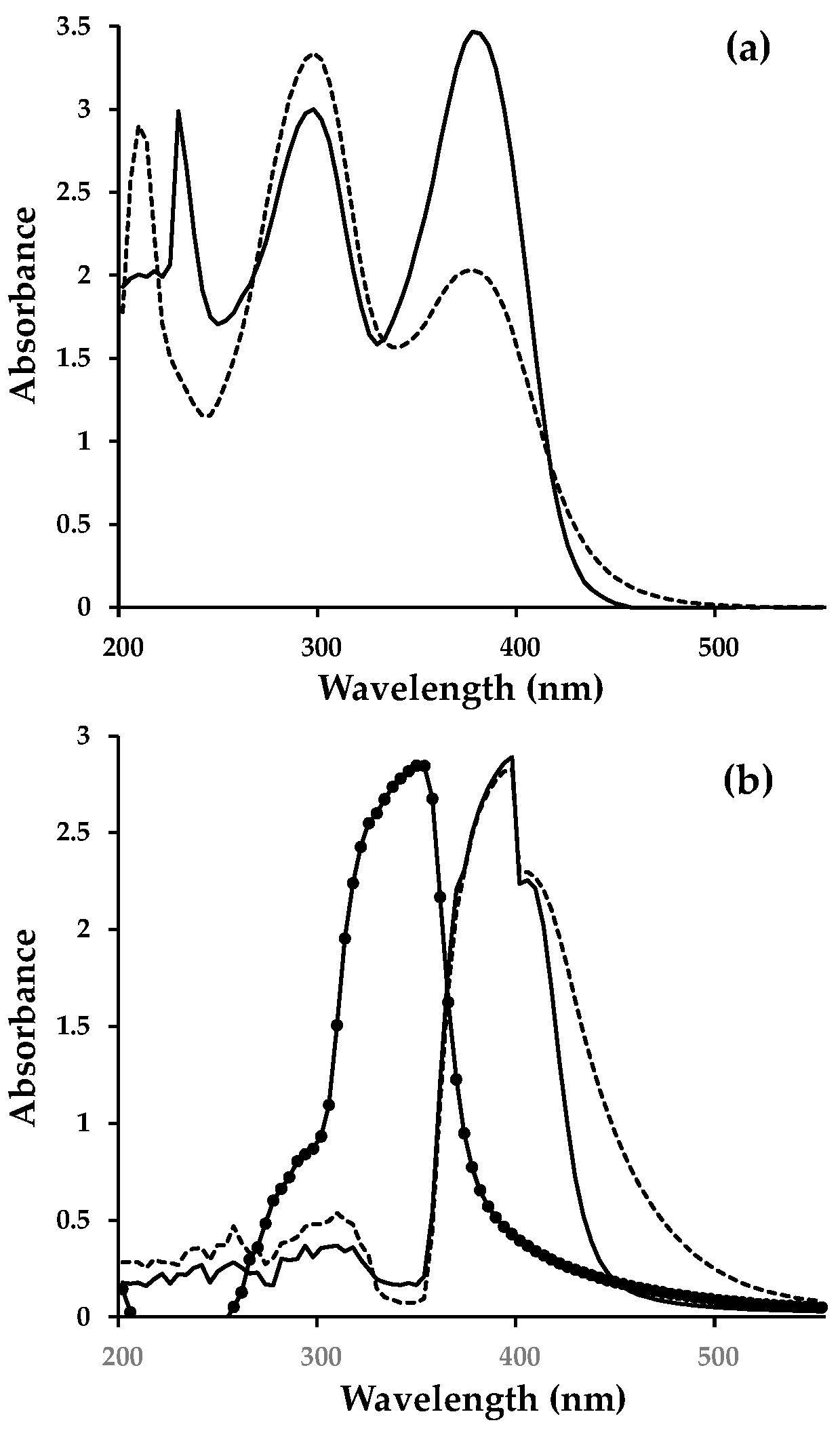
| Absorbance maxima/nm and (extinction coefficient/M−1 cm−1) | 296 (35,421) 376 (20,869) | 296 (25,718) 372 (35,218) |
| Ethanol solution absorption onset/nm | 502 | 456 |
| Ethanol solution HOMO-LUMO gap/eV | 2.47 | 2.72 |
| TiO2 adsorbed absorption onset/nm | 570 | 530 |
| TiO2 adsorbed HOMO-LUMO gap/eV | 2.18 | 2.34 |
| Device | Dye(s) | H (%) | FF | Jsc (mA/cm−2) | Voc (V) |
|---|---|---|---|---|---|
| Passive dyed | |||||
| A | (8) | 2.4 | 0.63 | 5.37 | 0.71 |
| B | (10) | 1.2 | 0.67 | 2.82 | 0.63 |
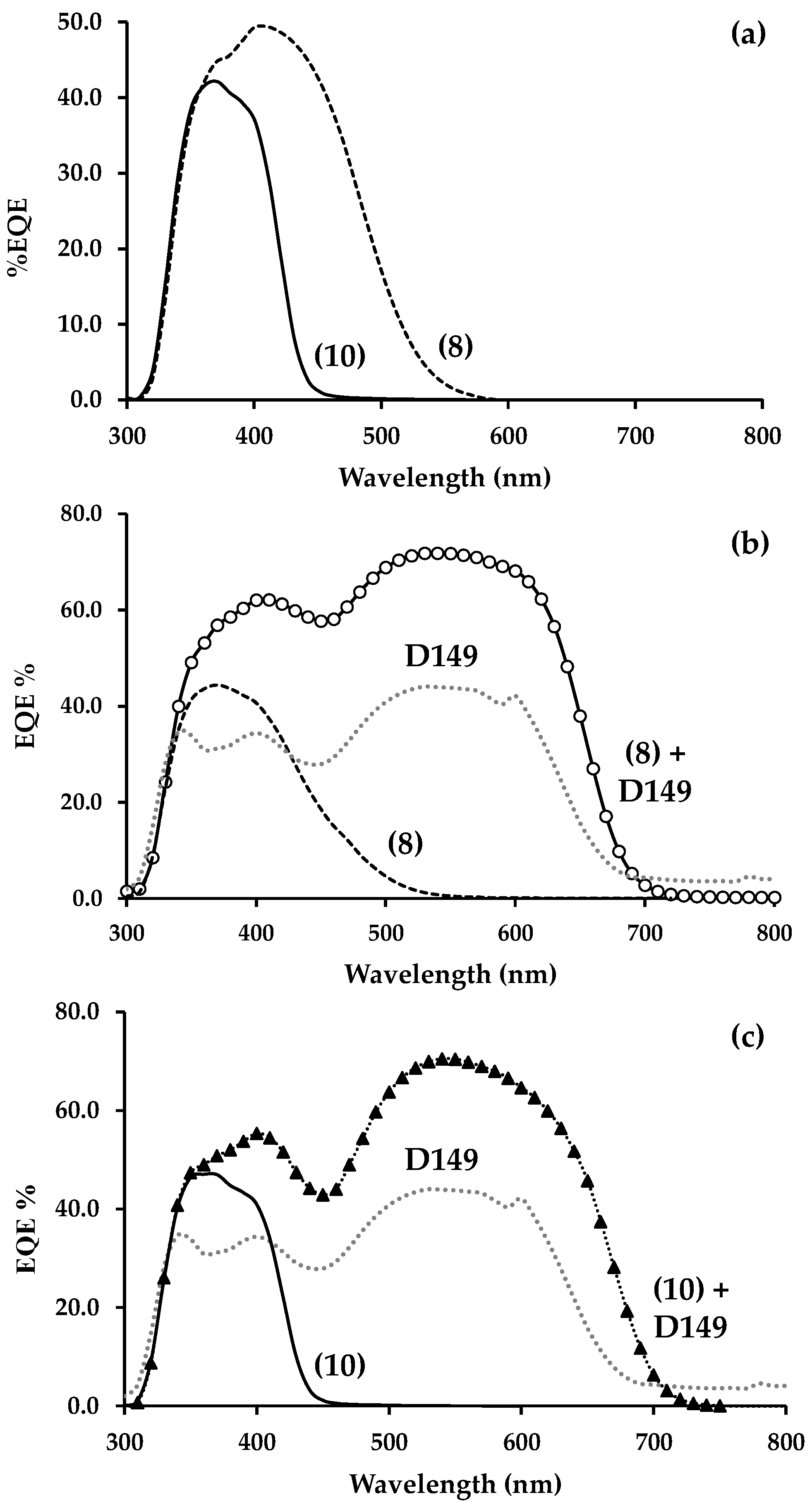
| C | D149 | 4.4 | 0.54 | 13.50 | 0.60 |
| Fast dyed | |||||
| D | N719 | 4.2 | 0.62 | 9.32 | 0.73 |
| E | (8) | 2.6 | 0.72 | 4.53 | 0.76 |
| F | (10) | 1.0 | 0.58 | 2.50 | 0.67 |
| G | D149 | 4.3 | 0.53 | 13.34 | 0.61 |
| H | (8) + D149 | 5.4 | 0.59 | 14.69 | 0.58 |
| K | (10) + D149 | 4.4 | 0.54 | 12.63 | 0.58 |
| L | (8) + N719 | 2.1 | 0.58 | 5.82 | 0.62 |
| M | (10) + N719 | 2.6 | 0.78 | 4.41 | 0.74 |
| Dye and Orientation | Dye-TiO2 Interactions | Approx. Angle of Dye to TiO2 Surface (Degrees) | Projected Surface Area of Dye on Surface (Å2) | |||
|---|---|---|---|---|---|---|
| Number and Type a | Distance (Å) | |||||
| DFT | MD and Standard Deviation | DFT | MD b | |||
| (8) horizontal | 2 × N--Ti 2 × C=O--Ti 1 × Cb--O 2 × C-OH--O | 2.27, 4.03 2.49, 2.56 1.53 2.55, 2.31 | 4.26 ± 0.54, 4.24 ± 0.56 3.82 ± 0.32, 3.90 ± 0.32 - 2.92 ± 0.41, 3.03 ± 0.41 | 5–10 | 6.33 ± 1.63 | 201 |
| (8) vertical | 2 × N--Ti 2 × C=O--Ti 2 × C-OH--O | 2.29, 6.82 2.46, 3.34 1.68, 4.00 | - - - | 75–80 | - | 89 |
| (10) horizontal | 2 × C=O--Ti 2 × C-OH--O | 2.37, 2.41 2.68, 3.45 | 3.79 ± 0.32, 3.80 ± 0.34 2.90 ± 0.42, 2.92 ± 0.43 | 5–10 | 7.42 ± 1.43 | 151 |
| (10) vertical | 2 × C=O--Ti 2 × C-OH--O | 2.26, 2.28 2.51, 4.02 | - - | 40–45 | - | 100 |
© 2020 by the authors. Licensee MDPI, Basel, Switzerland. This article is an open access article distributed under the terms and conditions of the Creative Commons Attribution (CC BY) license (http://creativecommons.org/licenses/by/4.0/).
Share and Cite
Holliman, P.J.; Mohsen, M.; Connell, A.; Kershaw, C.P.; Meza-Rojas, D.; Jones, E.W.; Geatches, D.; Sen, K.; Hsiao, Y.-W. Double Linker Triphenylamine Dyes for Dye-Sensitized Solar Cells. Energies 2020, 13, 4637. https://doi.org/10.3390/en13184637
Holliman PJ, Mohsen M, Connell A, Kershaw CP, Meza-Rojas D, Jones EW, Geatches D, Sen K, Hsiao Y-W. Double Linker Triphenylamine Dyes for Dye-Sensitized Solar Cells. Energies. 2020; 13(18):4637. https://doi.org/10.3390/en13184637
Chicago/Turabian StyleHolliman, Peter J., Moneer Mohsen, Arthur Connell, Christopher P. Kershaw, Diana Meza-Rojas, Eurig W. Jones, Dawn Geatches, Kakali Sen, and Ya-Wen Hsiao. 2020. "Double Linker Triphenylamine Dyes for Dye-Sensitized Solar Cells" Energies 13, no. 18: 4637. https://doi.org/10.3390/en13184637