
Abstract
Methods of fabricating and controlling organic light emitting diode (OLED) or photovoltaic layers effectively are paramount for achieving a functional and durable device. The deposited film needs to be uniform and homogeneous to avoid non-uniform luminescence in the OLED. Although methods of depositing the ultra-thin sub 100 nm layers within OLED are effective, they are relatively slow and expensive. This paper therefore demonstrates flexography as an alternative method for depositing the semiconductor layer for OLED onto glass substrate. In this case a proprietary semiconducting polyflourine dispersed in xylene was used. This material functions as the hole injecting layer. The low polymer concentration and requirement for aromatic solvent presented challenges for the process; conventional photopolymer printing plates degraded rapidly on contact with xylene and rubber printing plates were found to be sufficiently resilient. Through optimisation of printing parameters and surface modification of both the printing plate and substrate with UV/ozone exposure, a consistent sub-100 nm film was achieved. Flexographic printing will enable a substantial reduction in layer fabrication time, as well as allowing roll to roll mass production at lower cost. The research indicated within this paper will aid the progression of flexography as a viable cost effective method for OLED or display technology application through continuous printing of ultra-thin layers.
Export citation and abstract BibTeX RIS
1. Introduction
Since organic light emitting diode (OLED) technology was first developed in the 1950s as a simple anode, cathode and semiconductor material [1], commercial application has increased through widespread adoption of consumer electronics and industrial investment. Large businesses within the display technology industry (mobile telephones, televisions) have adopted OLED as their display of choice due to thinness and flexibility, higher contrast and improved efficiency, with operation voltages anywhere between 2 V and 10 V [2]. The recent surge in device efficiency and durability has been due to the research into new functional materials and fabrication technologies which has enabled thinner, more uniform films and new device architecture. This has also been the case through the advancement of organic photovoltaic devices where thin uniform conjugate polymer layers help to preserve and advance the device performance [3–5]. The use of such thin layers has given better device performance and enabled new applications. Kunic and Sego [2] covered the different structures of OLED that can be developed depending on device output and intended purpose. For instance, AM-OLED (active matrix OLED) has a TFT (thin film transistor) array which is ideal for larger displays while a PMOLED (passive matrix OLED) is a more simple structure where the anode and cathode strips are perpendicular to each other forming pixels where they intersect. It is with these changing properties of OLED architecture that the process of fabrication needs to be quick and simple to modify in order to meet the needs of the device. Inkjet printing has provided an interchangeable system where the outputted patterned film can be determined through computer aided design. Inkjet is not however ideal for mass production of OLED application as it is a slow process. Deganello [6] covered the techniques for printing layers for OLED and the advantages/disadvantages to each method. Conventional printing methods such as gravure, screen printing, flexography and lithography are defined by their need for a physical image carrier (printing plate or screen) [7, 8]. Deciding the appropriate technology to invest in is imperative in order to achieve reliability and a cost effective manufacturing process. Methods such as slot die coating may well produce uniform thin and continuous films but patterned designs, required for complex OLED systems, cannot be produced by these methods [9]. Screen printing is fast and patternable but variations in film thickness can lead to inconsistencies in the functioning OLED and typical thicknesses are in excess of those required for OLED applications [10–12]. Problems can occur also when it comes to technologies which incorporate small dots in the printing technology (engraved cells with gravure, mesh design with screen printing, droplets produced from inkjet printing).
Flexography is the process of depositing an ink or solution through use of a raised image plate carrier. Engraved cells on an anilox cylinder draw up the ink or solution from an ink bath. Excess material on the surface of the anilox is then scraped via a doctor blade, and the ink in the cells is then transferred to a raised image on a printing relief plate which is in turn transferred to the substrate which rolls alongside the printing plate through use of a substrate roller (figure 1). Variables associated with the flexographic printing process include; print speed, print force/engagement, anilox cell volume, anilox force/engagement as well as the solution and substrate properties. The primary means of controlling the amount of liquid transferred is the anilox cell volume and shape of the anilox cells. The ink capacity of the anilox cylinder is normally quoted in cubic centimeters of ink per meter squared of anilox surface which gives an indication of the maximum theoretical ink transfer. The flexibility of substrate parameters, as well as solution properties, makes flexography a desirable process for any graphics or functional printing process. Flexography has already been demonstrated to effectively as a method of depositing functional layers and patterns [12, 13].
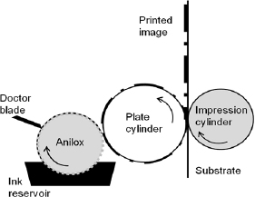
Figure 1. Flexographic printing process schematic.
Download figure:
Standard image High-resolution imageA key consideration in the printing of semiconducting polymers for OLEDs is the tendency of the polymers to require aromatic or chlorinated solvents as diluents. These solvents are problematic for flexographic printing due to high volatility. Furthermore, the low ink film thickness, when compared with conventional thicknesses for the process, requires a high level of dilution which in turn gives a low viscosity which is detrimental to the ink transfer mechanism which relies on shear thinning and recovery. This paper will demonstrate flexographic deposition of ultrathin continuous layers containing xylene based solution which has not previously been demonstrated. Through applying this approach, the time it takes to deposit the layers within OLED can be substantially reduced. Industrially it is typical for around 3600 linear metres of substrate to be coated per hour at high speed, which supersedes most other fabrication methods. With flexography, the interchangeable low-cost printing plate allows for a cost effective and simple approach to changing a patterned design to suit the intended OLED output device. For the required OLED efficacy, the films must be uniform and free from organic and inorganic contaminants which can lead to imperfections within the display. The operating parameters associated with flexography, such as the printing plate to substrate force, printing speed and plate treatment are therefore investigated and optimum printing conditions are deduced for a controlled printing process. It is common practice within display technology to employ techniques such as UV/Ozone in order to ensure substrates are free from contaminants such as oils. This will also change the wetting characteristics of the substrate which will have an effect on ink transfer and quality of the printed layer.
An investigation was undertaken into the optimum print settings to produce an even sub 100 nm film of semiconducting polyflourine dispersed in xylene. As well as varying the print settings, both substrate and plate materials were treated in a UV/Ozone environment to establish whether this could improve print quality. To evaluate the effect of UV/Ozone on the solid materials, surface energy characterisation was performed using contact angle measurement of deionised water, diiodomethane and ethylene glycol.
2. Experimental methods and materials
2.1. Materials
A proprietary semiconductor polymer F8-TFB (figure 2), developed by CDT Ltd (Cambridge Display Technology Ltd, Company Number 02672530) for use as a hole injection and electron blocking material was used in the tests. This was dissolved in xylene (general purpose grade, Fisher Scientific #A00367 CAS133-70–7). A lime glass substrate was used. This was supplied and cut to size (50 × 50 × 2 mm) by C.G.Toft Ltd in Swansea. A Conti-laserline CSX rubber printing plate (Continental) was used for printing as preliminary testing of xylene on conventional photopolymer printing plates showed rapid swelling and irreversible damage to the plate surface. Surface energy testing of the glass and polymer plate required the use of deionised water, ethylene glycol (99 + % extra pure, Acros Organics, 14675) and diiodomethane (A00360, Fisher Scientific).

Figure 2. F8-TFB polymer semiconductor material.
Download figure:
Standard image High-resolution image2.2. Methods
2.2.1. Solution manufacture and characterisation
In order to achieve the desired sub 100 nm dry film, a low polymer concentration of 8 mg ml−1 was dispersed in Xylene. The solution was placed in a glass bottle on a roller until fully dissolved (typically overnight to ensure complete mixture of polymer). The solution was then stored in an air conditioned laboratory out of direct sunlight.
The solution surface tension was then characterised by employing the pendant drop approach [14–16] determined through using a Fibrodat DAT1100 (Fibro System AB, Sweden). 1 ml of the solution was weighed using a scale to determine the density and 8 droplets of 8 μl volume were measured.
2.2.2. Determination of optimal printing parameters
Prior to treatment of the glass substrate and printing plate, the effect of printing parameters on deposition quality was investigated. The glass tiles were cleaned with IPA (isopropanol) in an ultrasonic bath for 3 min at 30 °C, rinsed with deionised water and then wiped dry using a lint free cloth.
The effect of flexographic printing parameters was investigated using an IGT F1 tester (figure 3).The device has a digital display through which the printing variables (printing speed, printing force, anilox force) can be varied. An anilox with a capacity of 12 c.c. m−2 was loaded into the system and the glass was placed onto a rigid substrate carrier which allowed it to pass under the printing plate when it rotated. Once the substrate was loaded, 1 ml of solution was added directly to the anilox where the surface of the anilox meets the doctor blade. To perform a print, the anilox was engaged with the plate and rotated. The plate was then engaged with the substrate and rotated further to produce a print. The glass was then transferred to a hot plate at 100 °C for 30 s to allow the solvent to fully evaporate. The settings were varied to determine optimum printing conditions. The anilox to printing plate force was kept constant at 150 N as preliminary testing showed sufficient transfer of solution between the anilox and printing plate. The printing plate to substrate force was varied from 20 N to 80 N in 20 N intervals, the printing force was varied from 20 N to 80 N in 20 N intervals and the printing speed was varied from 0.2 m s−1 to 1.0 m s−1 in 0.2 m s−1 intervals.
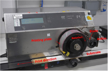
Figure 3. IGT F1 printability tester.
Download figure:
Standard image High-resolution imageThe topography of the printed samples was assessed using a white light interferometer (Veeco NT9300 wide area white light interferometer). The WLI was set to scan in PSI (phase shift interference mode) due to the sub 160 nm features present on the samples. Images were captured at the centre of the samples rendering a 3D topography plot for a projected area of 1.25 mm × 0.94 mm (a resolution of 640 × 480 pixels with sampling at 1.96 μm intervals). This showed the amount of dried polymer film remaining on the glass and the print quality. 2D profiles were captured for film continuity analysis and to compare varying print quality for each experiment. Film thickness was determined by making small cuts into the film. This allowed step height measurements to be made.
2.2.3. UV/Ozone treatment of substrate and plate and determination of wetting characteristics
The glass substrates were cleaned using IPA and exposed to UV/Ozone using Novascan™ PSD-UV system for 30, 90, 120, 240, 360, 480 and 600 s. Surface energy was determined through the Liftshitz-van Oss theory [17–19] where the contact angles of water, diiodomethane and ethylene glycol were inputted. The theory used the Liftshitz-van der Waals component ( ) and the acid–base component (
 ) to formulate the following equation:

The properties of the 3 liquids and reference properties of O-Xylene are shown in table 1 [20–22]. This is a diverse triplet with diiodomethane being purely dispersive and water and ethylene glycol being both polar and dispersive, but with differing negative and positive polar components. Using these values, together with the measured contact angles, the free surface energy of both the glass samples and the substrate were estimated. Measurements were taken for uncleaned, solvent cleaned and UV/Ozone treated glass. Dedicated equipment for measuring contact angle (Fibrodat) could not be used due to the inability of the equipment to measure low wetting angles. Therefore to perform the measurements, drops of liquid were applied via a micropipette and photographed with a camera. Contact angle was measured using image analysis software (Image J 1.46r, U.S. National Institutes of Health).
Table 1. Solution constants for water, diiodomethane and ethylene glycol.
| Liquid | Surface Tension (mN m−1) | ||||
|---|---|---|---|---|---|
| Total | Dispersive | Polar + | Polar − | ||
| 1 | Water | 72.8 | 21.8 | 65.0 | 10.0 |
| 2 | Di-idomethane | 50.8 | 50.8 | 0 | 0 |
| 3 | Ethylene glycol | 48 | 31.4 | 1.58 | 42.5 |
| 4 | O-Xylene | — | 30.1 | — | — |
2.2.4. Printing with UV/Ozone treated glass substrate and plates
Printing tests were repeated using glass substrates subjected to varying durations of UV/Ozone exposure. Furthermore, the flexographic plate was exposed to UV/Ozone and the effect on print quality assessed. Both the glass slides and the printing plates were exposed for up to 10 min with measurements taken on separate samples for different exposure times within this range to determine the effect on print quality.
3. Experimental results
3.1. Surface tension of semiconductor polymer solution
The determined surface tension of the solution of semiconducting polymer and xylene at the printing concentration of 0.8 mg ml−1 was found to be 24.0 mN m−1 with a standard deviation of 0.1. This surface tension was lower than that reported in literature for neat xylene. Furthermore as polymer concentration was increased, surface tension fell further as shown in figure 4. The surface tension calculated was low suggesting a tendency to spread readily over a substrate.
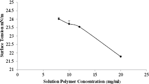
Figure 4. The effect of increasing polymer concentration on the surface tension of solution.
Download figure:
Standard image High-resolution image3.2. Effect of printing parameters on semiconductor layer uniformity using untreated substrate and printing plate
The initial testing using the IGT F1 printing system showed varying film quality and solution coverage through changing printing force and speed (figure 5). The effect of increasing print speed and print force can be seen in a series of WLI topography plots in figure 5 moving from left to right and from top to bottom respectively. Local height is indicated by a contour, with peaks in red and the lowest points in dark blue. It was observed from the images captured that at the lowest speed setting (0.2 m s−1) very little, if any, solution was deposited onto the glass substrate. The low print velocity was insufficient to cope with the rapid solvent evaporation, and the formulation dried on the plate. As the print speed was increased to 0.4 m s−1, more solution successfully transferred, but with significant gaps in coverage of the polymer layer. The print speed of 0.6 m s−1 once again showed more solution coverage but gaps were still present within the film. It was only at print speeds of 0.8 m s−1 that improved uniformity of polymer film was seen, but print speed of at least 1.0 m s−1 was required for a film to be formed. Increases in printing force did not show any substantial effect upon printed film quality and the defining factor was seen to be the increasing print speed. It is however important to note that even at optimal print settings, the semiconducting film was rough and uneven and did not fully cover the substrate (figure 6). This was not suitable for OLED manufacture and suggested that modification of print settings alone was not sufficient and that modification of the substrate and plate would have to be investigated.

Figure 5. White light images of the coatings performed with different flexographic printing speed and force (5 × white light magnification, 1.25 × 0.94 mm image sizes) (a; 20 N, b; 40 N, c; 60 N, d; 80 N). The figure shows better transfer and more even coverage is achieved through increasing print speed.
Download figure:
Standard image High-resolution image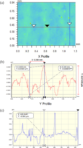
Figure 6. 2d profile of printed polymer film obtained through white light interferometry (print speed; 1.0 m s−1, print force; 40 N) (5 × white light magnification 1.25 × 0.94 mm image sizes) ((a) topography of sample surface with x and y coordinate lines, (b) x profile of sample surface, (c) y profile of sample surface).
Download figure:
Standard image High-resolution image3.3. Effect of UV/Ozone on wetting characteristics of glass substrate and printing plate
3.3.1. Glass substrate
The contact angles of 3 liquids (water, diiodomethane and ethylene glycol) on glass substrate and the effect of UV/Ozone on these are shown in figure 7. Both water and ethylene glycol showed a significant decrease in contact angle with UV/Ozone treatment, with longer treatment times giving greater reductions in contact angle for up to 6 min with contact angles below 5° indicative of almost complete wetting. The mechanisms that contribute towards this are thought to be removal of hydrocarbon contaminants as well as introduction of oxygen groups to the surface [23–25]. The contact angle of diiodomethane did not decrease to the same extent as deionised water or ethylene glycol but some reduction was observed with contact angles below 10° measured. The solid free surface energy of the glass tiles after various UV/Ozone exposure times was estimated and is shown in figure 8. Even after the first treatment of 30 s of UV/Ozone exposure, the glass substrate showed an increase in surface free energy from 47.1 mN m−1 to 51.7 mN m−1. The surface energy continued to increase to around 53.6 mN m−1 after 10 min of exposure. Through introduction of oxygen species and the removal of organic contaminants, an overall surface energy change of 6.5 mN m−1 was observed.
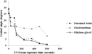
Figure 7. Contact angles of de-ionised water, diiodomethane and ethylene glycol measured after changing UV/Ozone exposure time.
Download figure:
Standard image High-resolution image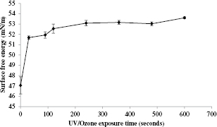
Figure 8. Surface free energy of glass substrate as a result of UV/Ozone exposure.
Download figure:
Standard image High-resolution image3.3.2. Contilaserline CSX
The contact angles of the 3 liquids (deionised water, diiodomethane and ethylene glycol) were determined and are plotted in figure 9. The plate material displayed higher contact angles than the glass substrate. Deionised water showed a decrease in contact angle from 100° to 50°. Diiodomethane did not show a consistent decrease in contact angle however. Within the first 30 s of exposure, the contact angle increased from 34° to 46° before decreasing to a value of 24° after 10 min of exposure. Ethylene glycol showed a slight decrease in contact angle from 68° to 63° after 10 s of exposure before increasing to 68° after 2 min and then showing a significant drop to 30° after 10 min of exposure. The increasing contact angle resulted in a changing surface energy of the rubber printing plate (figure 10). The overall surface free energy of the plate decreased after the first 30 s of exposure from 42 mN m−1 to 34 mN m−1. The surface energy then increased to 49 mN m−1 after the full 10 min of exposure. This reduction in surface energy was seen to be consistent over repeated measurement. Although the reason behind this phenomenon has yet to be fully understood, one explanation could point to oil-based chemicals such as waxes, present in some photopolymer plates, migrating to the surface of the plate through ultraviolet exposure [26]. This effect could then result in the decrease in surface energy which was observed in this experiment.
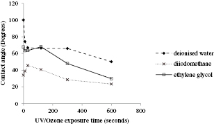
Figure 9. Contact angles of deionised water, diiodomethane and ethylene glycol on contilaserline CSX rubber printing plate after changing UV/Ozone exposure time.
Download figure:
Standard image High-resolution image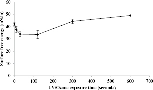
Figure 10. Changing surface free energy of the contilaserline CSX rubber printing plate with varying UV/Ozone exposure.
Download figure:
Standard image High-resolution image3.4. Effect of UV/Ozone treatment of glass substrate semiconductor substrate covering
3.4.1. Substrate covering after UV/Ozone exposed glass substrate
Surface topography plots for prints on UV/Ozone exposed glass are shown in figure 11 alongside corresponding prints made on untreated glass at a print force of 40 N and a varying print speed between 0.2 m s−1 and 1.0 m s−1. It was observed that generally more solution was deposited as a result of treatment of the glass. As the print speed increased to 0.4 m s−1 and 0.6 m s−1 more solution was deposited and spread across the glass surface due to the increased wetting nature. When printing at a speed of 1.0 m s−1, the film formed had fewer local peaks due to contaminants but more holes, or gaps, were observed due to the increased wetting nature of the surface.

Figure 11. Flexographic printed polymer film formed with changing print speed on glass tiles (a) before UV/Ozone exposure, (b) after 10 min of UV/Ozone exposure on the glass substrate (5 × white light magnification 1.25 × 0.94 mm image sizes).
Download figure:
Standard image High-resolution image3.4.2. Print quality after UV/Ozone exposed glass substrate and rubber printing plate
To exploit the decrease in surface energy of the printing plate, another film was printed after exposing the substrate and printing plate to UV/Ozone (for 10 min and 30 s respectively) and at a printing force of 40N and printing speed of 1.0 m s−1 (figure 12). The quality of the printed film increased considerably, with even coverage of polymer over the glass substrate. This improved film is thought to be a result of the greater surface energy differential between the glass substrate and rubber printing plate so as to make transfer to the glass more energetically favourable and thus induce greater solution transfer. The film thickness was determined through white light interferometry of cuts made into the film (as demonstrated in figure 13). A representative sample showed an average film thickness of 56 nm (with a standard deviation of 11 nm based on 9 measurements) which is ideal for the hole injection layer present within OLED.
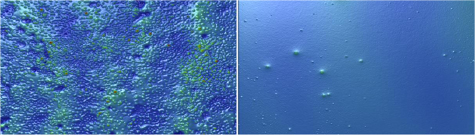
Figure 12. Film formed before (left) and after (right) 30 s UV/Ozone exposure of the contilaserline CSX printing plate (5 × white light magnification 1.25 × 0.94 mm image sizes).
Download figure:
Standard image High-resolution image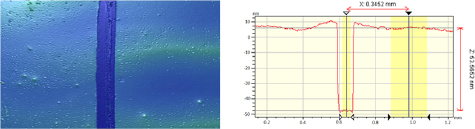
Figure 13. White light image and profile of cut made into film (5 × white light magnification, 1.25 × 0.94 mm image sizes).
Download figure:
Standard image High-resolution image
4. Conclusion
It has been deduced through this experimental research that controlling the quality of flexographically printed ultra-thin films can be achieved through an understanding of the surface properties of the rubber printing plate and substrate as well as the parameters associated with the flexographic printing process.
Printing a xylene based solution can be problematic due to the aggressive nature of the aromatic solvent as well as the low surface tension. This research provided a solution for the issue facing xylene, or similar, as the primary solvent within flexographic deposition through the use of Contilaserline CSX rubber printing plate whilst also considering the fast evaporation rate of the solvent. It should be noted that the CSX plate consists of EPDM rubber; while this is susceptible to attack from solvent, it is substantially more resistant than conventional photopolymer plates. Future work could investigate alternative combinations of plate and solvent.
Printing at high speeds (1.0 m s−1) produces a more uniform and better quality film whilst also achieving fast layer production ideal for suiting industrial needs. The main highlight of this research has been the optimisation of the printed layer through UV/Ozone treatment of the rubber printing plate whilst also improving the wetting nature of the glass substrate through removal of organic contaminants on the substrate surface. This work should be taken forward with studies on an industrial printing press in which the anilox and plate are continuously rewetting.
Acknowledgments
This work was supported by EPSRC (UK) Grants EP/J502248/1 and EP/M008827/1 and Cambridge Display Technology Ltd (Company Number 02672530).