
Valve Plate Structural Optimal Design and Flow Field Analysis for the Aviation Bidirectional Three-Port Piston Pump


1
School of Mechanical and Electrical Engineering, Xi’an University of Architecture and Technology, Xi’an 710055, China
2
Hydraulic Technology Research Institute, Xi’an Aeronautical Institute, Xi’an 710077, China
3
ZCCE, Faculty of Science and Engineering, Swansea University, Swansea SA1 8EN, UK
*
Authors to whom correspondence should be addressed.
Energies 2021, 14(11), 3246; https://doi.org/10.3390/en14113246
Submission received: 28 April 2021
/
Revised: 24 May 2021
/
Accepted: 29 May 2021
/
Published: 2 June 2021
(This article belongs to the Section L: Energy Sources)
Abstract
:This paper designed and optimized a bidirectional three-port valve plate structure for solving the matching problem of flow rate and pressure in the aerospace pump-controlled differential hydraulic cylinder. This design aims to make the valve plate work well under the bidirectional high-speed condition. The model was set up using dynamic mesh and sliding mesh, and the simulation is conducted by FLUENT. In addition, the flow field of inlet and outlet flow rate pulsations, pressure pulsation in cylinder, and non-dead-point transition zone of four cases are analyzed to optimize the valve plate in this work. The numerical results show that different angles of non-dead-point transition zones of the valve plate have a big impact on the performance of the piston pump. For example, the flow rate pulsation reaches the minimum when the angle of non-dead point transition zone is greater than or equal to the angle of a cylinder port. However, at this time, the closed compression would occur and the pressure inside the cylinder would rise rapidly as the piston moves to the non-dead point zone, thus resulting in serious pressure overshoot. In addition, if the angle of non-dead point transition zone is reduced within a certain range, the pressure overshoot will be reduced drastically, and the flow pulsation rate will rise a bit. The study suggests that it is necessary to adjust the angle of non-dead point transition zone to balance the pressure overshoot and flow pulsation of the pump to obtain the optimal kidney structure of the valve plate.
1. Introduction
An Electro-Hydrostatic actuator (EHA) is a popular energy-saving strategy for industrial machine design. It integrates a feedback unit, servo motor, control electronics, variable speed pump and a cylinder into a compact self-contained unit requiring only electronic power. It was originally developed for aerospace [1] and has been popular in other industries (for example, wind turbines, robotics, and transportation vehicles [2,3,4,5] as it offers safety, reliability, smaller size, and higher power efficiency over traditional hydraulic actuators [6,7].
One of the challenges in EHAs is to control asymmetrical inlet and outlet flow rate for two differential hydraulic chambers with different volumes [8,9]. Several works have been conducted to solve this issue. Caliskan used a shuttle valve to compensate for the uneven flowrate caused by asymmetric actuator in EHA system. Numerical simulation and experiments verify that this method can eliminate pressure oscillation in a certain speed range [10]. Ahmed et al. utilized a limited throttling valve alongside two pilot-operated check valves for balancing the flow rate of two chambers [11]. Wang et al. introduced a novel flow control circuit, discusses the stability of the system, and has good robustness [12]. Quan et al. summarized six methods of pump-controlled differential cylinder [13].
In order to balance the flow rate of pump and asymmetry cylinder, auxiliary components are required to be added into the hydraulic circuit. This may increase the weight of the whole system and it may not be a good option for aerospace applications, which have strict weight requirements [14]. The axial piston pump with three oil ports is another option to tackle the imbalance issue. For example, the three-port axial piston pump has been used by the advanced fifth-generation fighter F-35 in the United States. The large working oil port is connected to the rod-free chamber, the small working oil port is connected to the rod chamber, and the third oil port is connected to the accumulator [15,16]. This method enables the piston pump to control the differential cylinder directly, thus avoiding the use of additional components.
Several works have analyzed the performance of three-port axial piston pump in terms of serval parameters. For example, Zhang et al. simulated and analyzed the flowrate characteristics and measured the basic characteristics of the three-port piston pumps, such as the pressure, flowrate, and the noise under different rotational speeds on the test bench. This research lays a theoretical foundation for further developing the three-port piston pump [17]. Huang et al. investigated the dynamics and tested the performances of a three-port piston pump [18]. Quan et al. considered the movement characteristics of individual piston and compressibility of oil and analyzed the flowrate characteristics of the three-port piston pump [19]. Ge et al. uses the three-port piston pump to control the bucket rod hydraulic cylinder of excavator, which obtains high positioning accuracy and significantly reduces the energy consumption of the bucket rod hydraulic cylinder in operation under the condition of ensuring the controlled running speed [20]. He et al. analyzed the rotational speed and the inclination angle of the swash plate on pump displacement to investigate their impacts on the performance. For other parameters influencing the performance of the three-port axial piston pump, the non-dead point transition zone has a crucial impact on the performance of the pump [21]. Yang et al. analyzed the vibration damping structure of the non-dead transition zone through a single piston model in order to reduce the impact of the non-dead transition zone and found that reducing the precompression angle and increasing the damping groove can improve the performance of the piston pump [22]. Gao et al. proposed a variable displacement asymmetric piston pump, and the feasibility of this method is verified by experiment [23].
Computational Fluid Dynamic (CFD) is suitable for simulating and analyzing complex engineering problems such as fluid flow, heat exchange, and molecular transport, etc. [24,25]. Montenegro et al. used a mesh-to-mesh interpolation technique to simulate a rotative volumetric expander via CFD [26]. Alberto et al. used a dynamic grid technology and unsteady numerical methodology for the CFD simulation of Air-Operated Diaphragm Pump [27]. Mcnaughton et al. simulated the performance of turbines and their support structure, e.g., flow around simple, isolated, rotating shapes (cylinder, sphere, and cube) using sliding mesh technology [28]. In this study, both a dynamic mesh and a sliding mesh are used to simulate the motion of three-port piston pump. According to the numerical simulation results, the flow rate characteristics and pressure characteristics and flow field under the different non-dead point transition zone of the bidirectional axial piston pump are studied. The pump structure in this work provides an option for aerospace high-speed pump applications, which require higher stability and performance. The three-port axial piston pump is constructed and simulated using FLUENT. The results are validated using Taiyuan University of Technology’s experimental data [23]. The relevant flow characteristics that influence the performance of the pump are analyzed.
The structure of the paper is as follows: Section 2 presents the pump design and the Main geometric parameters of the three-port pump; Section 3 provides the details of the model setup; Section 4 illustrates the simulation results of the structure of the three-port axial piston pump and analyzed the influential factors on the performance of the pump. Finally, the summary and conclusions are presented.
2. Pump Design
The three-port piston pump (The structure is shown in Figure 1) studied in this paper is suitable for the aerospace field, with the characteristics of small displacement, high rotational speed, and bidirectional rotation. Different from the previous research, in order to achieve and maintain the stability of flow rate and pressure pulsation during bidirectional rotation, triangular grooves are arranged on both sides of the three ports of the valve plate, and the precompression angle in the dead center at the top and bottom is equal to the precompression angle (as shown in Figure 2b, and are equally divided by the connecting line between the dead centers at the top and bottom).
The three oil ports of the three-port piston pump are ports A, B, and C, respectively. In this figure, we can see that 9 pistons reciprocate in their respective cylinder chambers and rotate along with the cylinder. Assuming that the cylinder and pistons rotate clockwise with forward rotation, the pistons will pass through port B and port C from port A in turn during forward rotation, and then return to port A to reciprocate, while reverse rotation is the opposite. The main geometric parameters of the three-port plunger pump designed in this paper are shown in Table 1.
3. Model Setup
3.1. Parameters Setting for the Three-Port Valve Plate
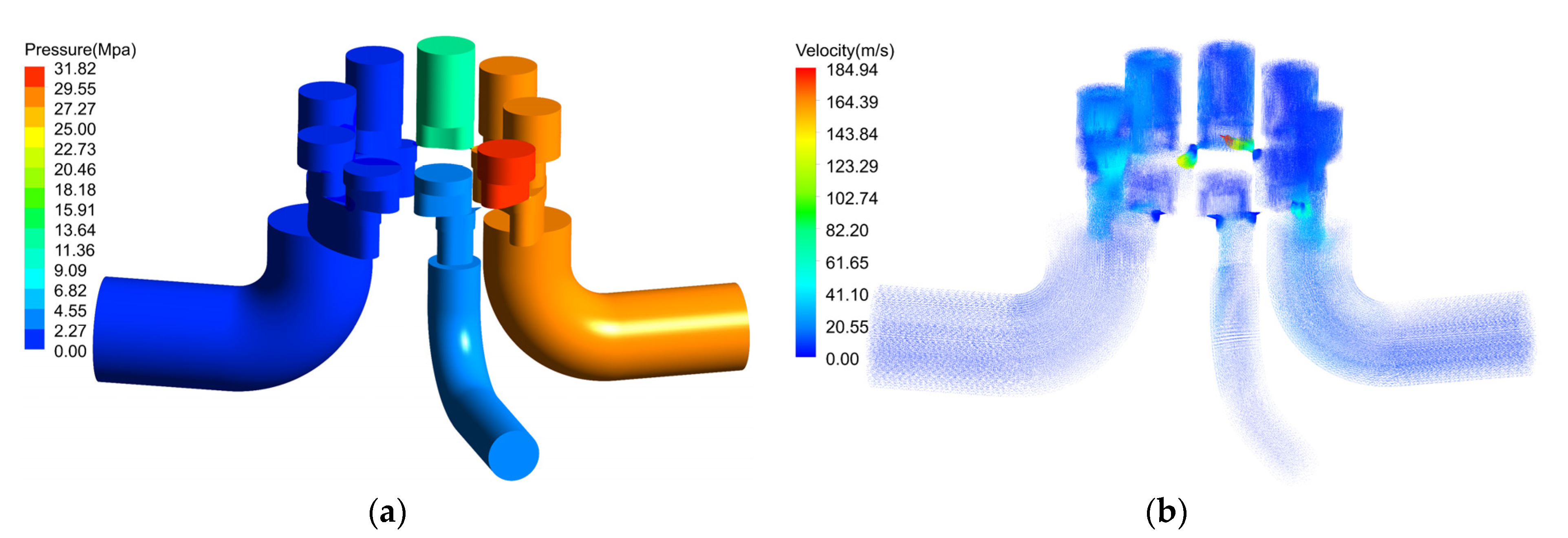
The 3D fluid domain of the bidirectional three-port axial piston pump used in this work is given in Figure 2a. There is a large pressure difference between the port A and port B (0.4 Mpa and 28 Mpa). When the piston is connected to two ports at the same time, the fluid will flow from the high-pressure area to the low-pressure area, which will affect the flow rate of the two working ports and produce fluid noise. Figure 2b shows the three-oil port valve plate structure designed in this paper. , and α3 denote the angles of the top dead point transition zone, the bottom dead point transition zone, and the non-dead point transition zone, respectively. In order to ensure the stability of the performance of the piston pump in the forward and reverse rotation, a triangular vibration damping groove is designed at both sides of the three ports, and the connecting lines above the dead point transition zone and the bottom dead point are symmetrically distributed.
The angles of the top and bottom dead point transition zone are set exactly equal to the angles of a cylinder port, and α3 is adjusted to minimize the impact of non-dead zone on pump performance. Four different port plate structures were studied in this work, whereby case 0 is set to be α1 = α2 = α3 = αp, increasing αB will decrease α3, and taking case 0 as the reference, α3 in case 1, case 2, and case 3 is decreased by 2, 4, and 6 degrees, respectively.
3.2. Dynamic Mesh and Sliding Mesh
The motion state of the axial piston pump is complicated. In order to make the simulation results more accurate, it is necessary to use different meshing methods for each part when meshing the three-dimensional geometric model. In this work, the tubes and the cylinder chambers are divided into hexahedral meshes by sweeping, and the other parts adopted tetrahedral meshes. Due to the large pressure gradient at the triangular grooves, local finer mesh is required. Meshes are shown in Figure 3. The grid independence analysis of this pump fluid domain is carried out, and the final grid number is set to be 2.3 × 10⁶.
Sliding mesh technology is capable of simulating both periodic and aperiodic motion, and it is suitable for unsteady calculation. When using this technology, it is necessary to match the interface between the rotating part and the stationary part correctly to transmit data between the two different parts, and then set the rotation speed of the pistons in the cell condition dialog box. In the process of simulation calculation, the solver will be re-matched at each calculation step [29]. In this paper, the sliding mesh technology is mainly used to simulate the periodic rotation of nine pistons, where the piston pump valve plate and tubes are stationary parts, the cylinder chambers are moving parts, and the rotating speed of mesh motion is 16,000 rpm, which is set to have no sliding boundary.
Dynamic mesh technology is mainly used to realize the movement of a certain boundary or object in the model. FLUENT provides three dynamic meshes. Among remeshing, spring, and layering dynamic meshes, the layering method can simulate the reciprocating motion of the pistons accurately and is suitable for hexahedral mesh. Based on the height of mesh layer, when the mesh layer adjacent to the boundary is compressed to a certain height during compression, the mesh adjacent to the boundary will be deleted. On the contrary, when the mesh layer adjacent to the boundary is stretched to be greater than the set height, this method can simulate the reciprocating movement of the piston inside the cylinder chamber [30].
In order to motivate the reciprocating motion of the piston, the speed function is then written in C++ and is compiled into Fluent.
The rotational speed of piston is:
The reciprocating speed of piston is given by:
where: R is the standard pitch diameter; is the angle between the initial position of the piston and the top dead center, and β is the wash plate inclination angle.
3.3. Verification of Simulation Method
The axial piston pump with a three-port structure was proposed by the Taiyuan University of Technology and part of the research was done. The pump they studied has a low speed (500–2000 rpm) and large displacement (45 rev/min) and is proposed for general engineering fields. The three-port piston pump studied in this paper is proposed particularly for the aerospace application, which has a smaller displacement (2.25 mL/rev) and higher rotation speed (16,000 rpm). Due to the high experimental cost and the long prototype processing cycle, the piston pump studied in this paper has no experimental data at present. In order to verify and validate the model in this paper, we used the same parameters (shown in Table 2) used in the work [23] and the simulation results are compared.
Figure 4a is the structure of valve plate in the work of [23], port A is the oil suction port, ports B and C are the oil discharge ports. Figure 4b is the flow comparison between CFD and port B in the paper. The model verified this time is the same as that in the work of [23]. The model established in this paper does not consider the external leakage of oil film and slipper-swash plate and pistons, so there is a slight deviation between the CFD simulation result and the data from the work of [23], but the comparison deviation is within a reasonable range [31,32,33], and the general trend and pulsation of flow rate are basically the same, which can verify the correctness of the simulation method adopted in this paper.
3.4. Boundary Conditions
In the three-dimensional fluid domain model of the piston pump shown in Figure 2a, when the rotational speed is as high as 16,000 rpm, the cylinder chambers and the triangular damping grooves are turbulent, so it is necessary to select the turbulence model in the simulation. Among the turbulence models provided by FLUENT, the standard k-ε model has been widely used for its high accuracy, stability, and economy [34]. By solving the turbulence dissipation rate equation of the turbulence kinetic energy equation, the values of k and ε can be obtained.
According to the operating characteristics of the piston pump, the transient calculation is adopted, and both of the inlet and the outlets are set to be pressure boundary conditions. During forward rotation, the inlet (port A) gauge total pressure value is set to 0.4 Mpa, outlet1 (port B) gauge pressure value to 28 Mpa, and outlet2 (port C) gauge pressure to 3 Mpa; when reversing, the outlet (port A) gauge pressure is set to 0.4 Mpa, inlet1 (port B) gauge total pressure to 28 Mpa, and inlet2 (port C) gauge total pressure to 3 Mpa. The rotation speed of the cylinder is 16,000 rpm, and the walls have no slip boundary condition, while the near wall treatment adopted the scalable wall function.
Nine pistons pump every 40 degrees for a cycle, and ten cycles are calculated, as the calculation of the first cycle is unstable and will not be adopted. The time step size has a great influence on the simulation results, and a time step size sensitivity analysis has been carried out. When the time step is set to 1.041667 × 10⁻⁵ s, for each step of the calculation, the cylinder rotates 1 degree, and ten cycles are 400 degrees, so the number of time steps is set to 400.
The low compressibility of oil is considered. The equation of oil compressibility is:
The speed of sound:
where K is the bulk modulus, is the reference liquid pressure (absolute), and is the reference liquid density (density at reference pressure, ).
4. Results and Discussion
This section analyzes the flow characteristics of the non-dead point transition zone in the three-port piston pump for four cases in terms of flow rate pulsation, pressure pulsation, and internal flow field.
4.1. Flow Rate Analysis
Ports A and B of three-port piston pump are connected to two chambers of the asymmetric cylinder. The motion characteristics of the asymmetric cylinder depend on the performance of port A and port B. Port C is connected to oil tank to balance the flow difference between two chambers. Therefore, the flow characteristics of port A and B are mainly considered when designing a three-port pump, and port C is not considered.
4.1.1. Numerical Simulation Flow Rate Analysis
The piston pump with four different valve plate structures (four different cases: Case 0–3), which works under forward rotation, is simulated using Fluent. The flow rate of ports A and B are shown in Figure 5. As we can see from the figure, the flow rates at port A of the four cases are very close. This is because we only change the structure of port B, and the structure of port A is not changed.
Unlike port A, the flow rates of port B are changed significantly. When αB increases, the time when the flow rate reaches the maximum and minimum values will lag accordingly, and the maximum value will also increase with the increase of αB, and the increase rate will gradually decrease. It can be seen from Table 3, the maximum values of Case 1, Case 2, and Case 3 increase by 0.28%, 0.44%, and 0.58%, respectively, compared with Case 0. In addition, the minimal flow rate will decrease with the increase of αB, and the rate of decrease will gradually increase. The minimal flow rates of Case 1, Case 2, and Case 3 are reduced by 0.19%, 0.94%, and 6.57%, respectively, compared with Case 0.
The flow pulsation rate is an important parameter to measure the performance of the piston pump, which is calculated from the maximum value Qmax and the minimum value Qmin of the flow rate in a cycle: . As Qmax and Qmin changed with the variations of the structure, the flow pulsation rates of four cases also changed accordingly. Case 1 and Case 2 have an increase of less than 2% compared to Case 0, but Case 3 has an increase of 7.05%.
Therefore, the flow pulsation rate would be greater with the smaller αB for flow pulsation at port B. When αB is increased to a certain extent, the flow pulsation rate will increase rapidly.
4.1.2. Theoretical Flow Rate Analysis
The theoretical flow solutions are calculated using the formula below [35]:
where dp is the piston diameter.
The theoretical flow pulsation of each oil port of the three-port piston pump of case 2 is shown in Figure 6a,b. In the figure, the total flows of nine pistons of port A and B are 1.52% and 33.4%, respectively. The total flow of port B (33.4%) is much higher than that of the traditional symmetrical pump (only 1.5%). This is because we improved the size of the kidney of port B for this bidirectional three-port axial piston pump structure. This comparison is under the same condition of nine pistons and does not consider triangular vibration damping groove, backflow, and internal leakage.
For the geometric pulsation calculation caused by the valve plate structure, the triangular groove is not considered. In the CFD numerical simulation, the triangular groove is set at both sides of the three kidneys to reduce the pulsation, so the pulsation result obtained by numerical simulation is lower than the theoretical calculation value.
4.2. Pressure Analysis
When the piston moves from port B to port C, the flow area decreases continuously, and the internal volume of the cylinder chamber is also reduced. Closed compression occurs inside the cylinder chamber, and the pressure rises rapidly, forming a pressure overshoot. The pressure pulsation inside the cylinder chamber of Case 0 to Case 3 is shown in Figure 7. The angle of the cylinder port is equal to the angle of the transition zone of the non-dead point of the Case 0. When the piston moves to the non-dead point, the kidney of the piston does not communicate with the kidney of the port B and C at all, and the flow area reaches the minimum value. At this time, the pressure inside the piston cavity reaches the maximum value of 201.7 MPa, and the pressure overshoot is too large. The angles of the non-dead point transition zones from Case 1 to Case 3 are all smaller than the angle of a cylinder port. When moving to the non-dead point, they are not completely separated from the B and C ports, and the maximum pressure value is less than the maximum value of Case 0, and it is reduced by 71.55%, 83.53%, and 85.11%, respectively, compared with Case 0.
The value of the pressure overshoot is shown in Table 4. Based on the flow pulsation analysis mentioned above, it can be concluded that although the flow pulsation rate of Case 0 is small, but the pressure overshoot reaches 607.7%. Excessive pressure overshoot reduces the life of the pump, produces noise, and affects the overall performance of the pump. Case 1 to Case 3 prolonged the time of backflow, and the pressure overshoot was greatly reduced. The pressure overshoot from Case 0 to Case 2 is decreased by 591.3%, while the flow pulsation rate is only increased by 2.39%. At this time, the maximum pressure has been reduced to a certain extent. When the angle of transition zone continues to decrease, the pressure overshoot will no longer decrease significantly, but the flow pulsation rate would be increased instead. Therefore, when designing the three-port valve plate, it is necessary to consider the structural critical value of obtaining the best flow pulsation rate and pressure overshoot.
4.3. Flow Field Analysis
Figure 8a,b shows the pressure contours and velocity vector diagram of the whole pump when the piston pump rotates 20 degrees. At this time, the piston just moves to the top dead point, and the triangular grooves of A and B kidneys are connected at the same time. The high-pressure oil at port B flows backward into the cylinder chamber, the pressure in the cylinder chamber rises rapidly, the maximum speed also appears at the triangular groove at the top dead point, the piston in the transition zone of non-dead point has not yet touched the triangular groove of C port, and the internal volume of cylinder chamber is continuously compressed, so the pressure overshoot appears at this moment.
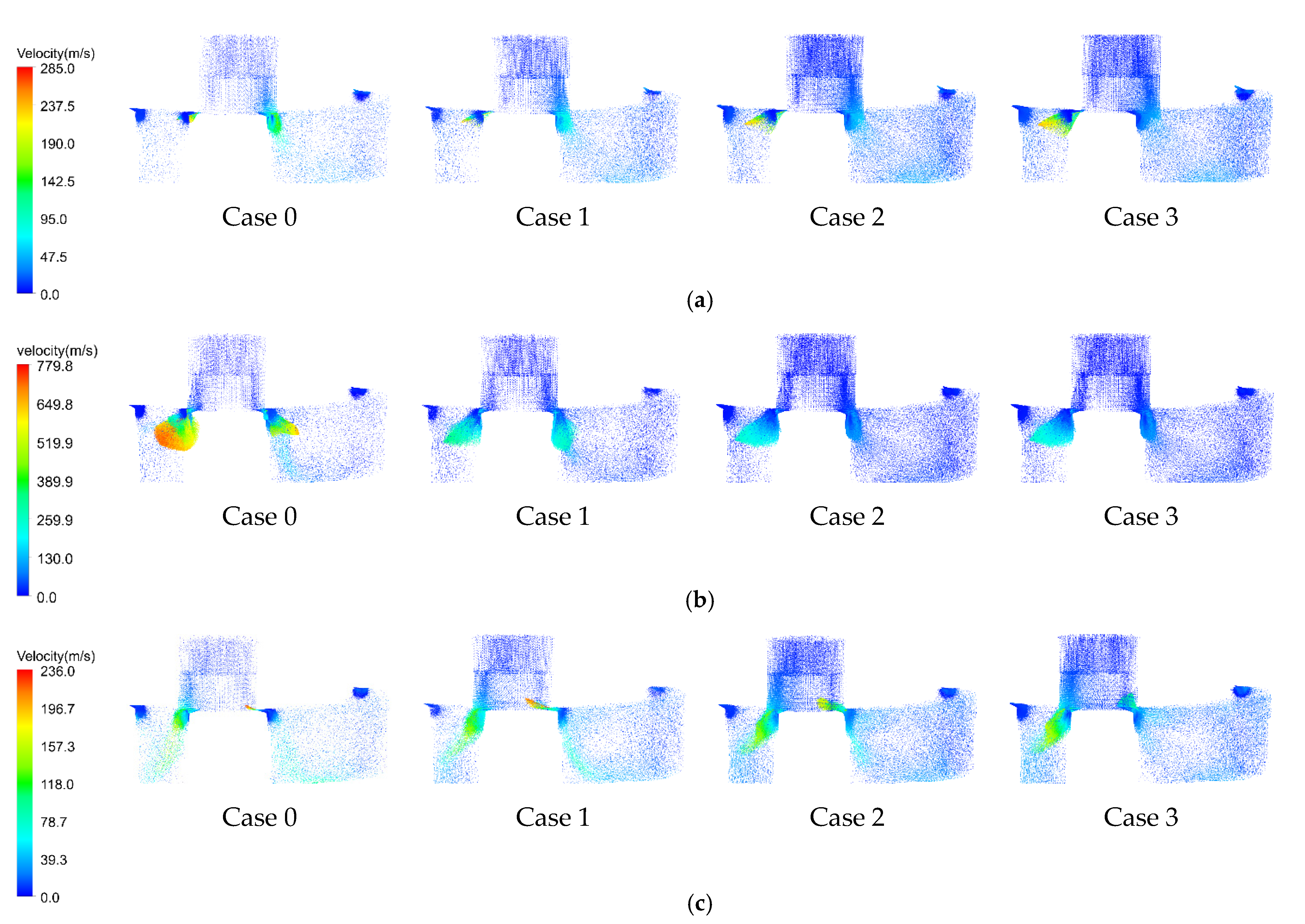
Figure 9a shows the velocity vector diagram when the piston pump rotates 23 degrees. At this time, the pistons in the non-dead-point transition zone of four cases are connected with the triangular groove of port C, and the high-pressure oil is rapidly discharged into port C, in which the maximum velocity of Case 0 reaches 285 m/s, the maximum velocity of Case 1 reaches 244.9 m/s, and the maximum velocities of Case 2 and Case 3 decrease in turn, but the decrease rate is not significant. Figure 9b shows the speed vector diagram when the piston pump rotates 27 degrees. At this time, the pistons in the non-dead point transition zone of the four cases are connected to the two ports B and C at the same time, and the backflow occurs between the two ports, resulting in the increase of flow pulsation. Due to the serious pressure overshoot of case 0, the maximum speed reaches 779.8 m/s, which brings great pressure and flow rate shocks and reduces the overall life of the pump. Figure 9c shows the velocity vector diagram when the piston pump rotates 31 degrees. At this time, the piston in the non-dead point transition zone of Case 0 will be separated from port B, and Case 1 to Case 3 will be separated from port B in turn. As the flow area between the piston and port B is smaller, the backflow will be smaller too.
When the angle of cylinder port is equal to the angle of non-dead-point transition zone, a larger flow rate will be generated when the piston is connected to two ports at the same time. With the decrease of the angle of transition zone, the backflow velocity would also be decreased. The smaller the angle of the transition zone, the longer the backflow time and the greater the flow pulsation.
4.4. Comparison between Forward and Reverse Rotation
For the bidirectional three-port axial piston pump, in order to ensure the stable performance of the pump under forward rotation and reverse rotation working conditions, the symmetry based on the main shaft should be considered when designing the transition zone between the top and bottom dead points of the valve plate. The nine-pistons pump has a cycle every 40°, the initial position of p1 is at the bottom dead point, and the position distribution of each piston is shown in Figure 10. Figure 11 shows the flow rate comparison of port A and B under forward and reverse working conditions. During forward rotation, the pressure at port A is 0.4 MPa and port C is 3 MPa; the pressure difference is small, so the flow rate is small. While in reverse rotation, the pressure at port A is 28 MPa, port C is 3 MPa, and the pressure difference is large. When the piston moves to the transition zone of the bottom dead point, the backflow is more serious than the forward rotation, so the flow rate under reverse rotation is lower than that forward rotation. When the pumps rotate by 20°, P5 in the forward rotation condition and P6 in the reverse rotation condition move to the top dead point. Although the working pressure at port A and B is reversed, the pressure difference remains unchanged. The flow rate difference is caused by the backward flow of triangular groove at port A during reverse rotation. The flow rate comparison diagram of port B under the working conditions of forward and reverse rotation is shown in Figure 11. The difference between the maximum and minimum flow rate in reverse rotation is greater than that in forward rotation due to the fact that the pressure in port B is low during reverse rotation, and no backflow occurs.
5. Conclusions
In this paper, a structure of EHA three-port piston pump valve plate was designed and optimized, and the model was simulated by Fluent. After analyzing the simulation results, the following conclusions can be drawn:
- (1)
- Compared with the traditional symmetrical piston pump, the three-port piston pump valve plate has an extra non-dead-point transition zone. The structure of the non-dead-point transition zone has a great influence on the performance of the pump. Based on the analysis of the flow characteristics, pressure characteristics, and internal flow field of the pump for four different valve plate structures, it can be concluded that when the angle of the non-dead-point transition zone is equal to the angle of a cylinder port, a smaller flow pulsation rate can be obtained; however, closed compression will happen inside the cylinder chamber and produces serious pressure overshoot, thus affecting the performance of the pump. When the angle of the non-dead-point transition zone decreases continuously, the pressure overshoot will decrease rapidly, and the flow pulsation rate will increase slightly. When the angle of the non-dead-point transition zone decreases to a certain level, the pressure overshoot will no longer decrease obviously, but the flow pulsation rate will start to increase significantly.
- (2)
- In order to ensure stable performances of the pump under forward and reverse working conditions, the transition zone between the top and bottom dead points should be symmetrical around the main shaft. The flow rate of the two working ports in forward and reverse rotation is affected by the working pressure, and the flow rate in forward and reverse rotation will have a small difference due to the change of pressure difference in the top and bottom dead points transition zone.
Author Contributions
Conceptualization, X.L. and Y.X.; methodology, X.L.; software, Y.X. and J.T.; validation, X.L., Y.X. and J.T.; formal analysis, X.L.; investigation, Y.X.; resources, X.L.; data curation, X.L.; writing—original draft preparation, X.L.; writing—review and editing, D.X.; visualization, X.L.; supervision, X.L.; project administration, X.L.; funding acquisition, X.L. All authors have read and agreed to the published version of the manuscript.
Funding
This research received no external funding.
Institutional Review Board Statement
Not applicable.
Informed Consent Statement
Not applicable.
Data Availability Statement
Data is contained within the article.
Acknowledgments
Tao would like to acknowledge the support of the Flow field simulation of valve pair of series asymmetric axial piston pump(20JK0698). Xiao would like to acknowledge the support of the The Royal Society International Exchanges 2019 Cost Share (IEC\NSFC\191037).
Conflicts of Interest
The authors declare no conflict of interest.
References
- Navarro, R. Performance of an Electro-Hydrostatic Actuator on the F-18 Systems Research Aircraft; Technical Report No. NASA/TM-97–206224; Dryden Flight Research Center, NASA: Los Angeles, CA, USA, 1997.
- Karanović, V.; Jocanović, M.; Jovanović, V. Review of development stages in the conceptual design of an electro-hydrostatic actuator for robotics. Acta Polytech. Hung. 2014, 11, 59–79. [Google Scholar]
- Jensen, S.C.; Jenney, G.D.; Dawson, D. Flight test experience with an electromechanical actuator on the F-18 systems research aircraft. In Proceedings of the 19th Digital Avionics Systems Conference, Philadelphia, PA, USA, 7–13 October 2000. [Google Scholar]
- Miller, T.B. Preliminary Investigation on Battery Sizing Investigation for Thrust Vector Control on Ares I and Ares V Launch Vehicles; Technical Report No.: NASA/TM-2011-216899; NASA Glenn Research Center: Cleveland, OH, USA, 2011.
- Kaminaga, H.; Ono, J.; Nakashima, Y.; Nakamura, Y. Development of backdrivable hydraulic joint mechanism for knee joint of humanoid robots. In Proceedings of the IEEE International Conference on Robotics and Automation, Kobe, Japan, 12–17 May 2009; pp. 1577–1582. [Google Scholar]
- Alle, N.; Hiremath, S.S.; Makaram, S.; Subramaniam, K.; Talukdar, A. Review on electro hydrostatic actuator for flight control. Int. J. Fluid Power 2016, 17, 125–145. [Google Scholar] [CrossRef]
- Chao, Q.; Zhang, J.; Xu, B.; Huang, H.; Zhai, J. Effects of inclined cylinder ports on gaseous cavitation of high-speed electro-hydrostatic actuator pumps: A numerical study. Eng. Appl. Comput. Fluid Mech. 2019, 13, 245–253. [Google Scholar] [CrossRef] [Green Version]
- Quan, Z.; Long, Q.; Zhang, J. Review of energy efficient direct pump controlled cylinder electro-hydraulic technology. Renew Sustain. Energy Rev. 2014, 35, 336–346. [Google Scholar] [CrossRef]
- Ketelsen, S.; Padovani, D.; Andersen, T.O.; Ebbesen, M.K.; Schmidt, L. Classification and review of pump-controlled differential cylinder drives. Energies 2019, 12, 1293. [Google Scholar] [CrossRef] [Green Version]
- Çalışkan, H.; Balkan, T.; Platin, B.E. A Complete Analysis and a Novel Solution for Instability in Pump Controlled Asymmetric Actuators. J. Dyn. Syst. Meas. Control 2015, 137, 091008. [Google Scholar] [CrossRef]
- Imam, A.; Rafiq, M.; Jalayeri, E.; Sepehri, N. Design, Implementation and Evaluation of a Pump-Controlled Circuit for Single Rod Actuators. Actuators 2017, 6, 10. [Google Scholar] [CrossRef] [Green Version]
- Wang, L.K.; Book, W.J.; Huggins, J.D. A hydraulic circuit for single rod cylinders. J. Dyn. Syst. Meas. Control 2011, 134, 011019. [Google Scholar] [CrossRef] [Green Version]
- Quan, L.; Neubert, T.; Helduser, S. Dynamic performance of electro-hydraulic servo system with speed variable pumps. Jixie Gongcheng Xuebao (Chin. J. Mech. Eng.) 2003, 39, 13–17. [Google Scholar] [CrossRef]
- Wensheng, Z. Research on Dynamic Characteristics of Aviation High Pressure Variable Piston Pump. Master’s Thesis, Shaanxi University of Technology, Hanzhong, China, 2020. [Google Scholar]
- Wiegand, C. F-35 Air Vehicle Technology Overview. In Proceedings of the 2018 Aviation Technology, Integration, and Operations Conference, Atlanta, GA, USA, 25–29 June 2018. [Google Scholar]
- Robbins, D.; Bobalik, J.; De Stena, D.; Martin, N.; Plag, K.; Rail, K.; Wall, K. F-35 Subsystems Design, Development & Verification. In Proceedings of the 2018 Aviation Technology, Integration, and Operations Conference, Atlanta, GA, USA, 25–29 June 2018. [Google Scholar]
- Zhang, X.; Quan, L.; Yang, Y.; Wang, C. Output Characteristics of a Series Three-port Axial Piston Pump. Chin. J. Mech. Eng. 2012, 25, 498–505. [Google Scholar] [CrossRef]
- Huang, J.; Zhao, H.; Quan, L.; Zhang, X. Development of an asymmetric axial piston pump for displacement-controlled system. Proc. Inst. Mech. Eng. Part C J. Mech. Eng. Sci. 2014, 228, 418–1430. [Google Scholar] [CrossRef]
- Long, Q.; Yang, Y.; Xuwei, H. Simulation and experimental research on the axial piston pump with series three-windows in valve plate. In Proceedings of the 2011 International Conference on Fluid Power and Mechatronics, Beijing, China, 17–20 August 2011; pp. 71–76. [Google Scholar] [CrossRef]
- Quan, L.; Ge, L.; Wang, C.; Li, B.; Zhao, B.; Lu, Z. Experiment Study on the Characteristics of Speed-variable Asymmetric Pump Driven Excavator Arm. J. Mech. Eng. 2017, 53, 210–216. [Google Scholar]
- Wei, H.E.; Jia-Hai, H.U.A.N.G.; Hui-Min, H.A.O.; Long, Q.U.A.N. Research on Dynamic Characteristics of Variable-displacement Asymmetric Axial Piston Pump. Chin. Hydraul. Pneum. 2019, 10, 20–25. [Google Scholar]
- Yang, Y.; Quan, L.; Yang, J. Pressure pulsation characteristic analysis of the no-dead spots transition zone between flow distribution windows of axial piston pump. J. Mech. Eng. 2011, 47, 128–134. [Google Scholar] [CrossRef]
- Gao, Y.; Cheng, J.; Huang, J.; Quan, L. Simulation Analysis and Test of Variable-displacement Asymmetric Axial Piston Pump. Appl. Sci. 2017, 7, 328. [Google Scholar] [CrossRef] [Green Version]
- Arzamendi, G.; Diéguez, P.M.; Montes, M.; Odriozola, J.A.; Sousa-Aguiar, E.F.; Gandía, L.M. Computational fluid dynamics study of heat transfer in a microchannel reactor for low-temperature Fischer–Tropsch synthesis. Chem. Eng. J. 2010, 160, 915–922. [Google Scholar] [CrossRef]
- Sivertsen, B.R.; Djilali, N. CFD-based modelling of proton exchange membrane fuel cells. J. Power Sources 2005, 141, 65–78. [Google Scholar] [CrossRef]
- Montenegro, G.; Della, T.A.; Onorati, A.; Broggi, D.; Schlager, G.; Benatzky, C. CFD Simulation of a Sliding Vane Expander Operating Inside a Small Scale ORC for Low Temperature Waste Heat Recovery. SAE Tech. Pap. 2014. [Google Scholar] [CrossRef]
- Alberto, M.B.; Manuel, F.O.J.; Andrés, M.F. Numerical methodology for the CFD simulation of diaphragm volumetric pumps. Int. J. Mech. Sci. 2019, 150, 322–336. [Google Scholar] [CrossRef]
- McNaughton, J.; Afgan, I.; Apsley, D.D.; Rolfo, S.; Stallard, T.; Stansby, P.K. A simple sliding-mesh interface procedure and its application to the CFD simulation of a tidal-stream turbine. Int. J. Numer. Methods Fluids 2014, 74, 250–269. [Google Scholar] [CrossRef]
- Steijl, R.; Barakos, G. Sliding mesh algorithm for CFD analysis of helicopter rotor–fuselage aerodynamics. Int. J. Numer. Methods Fluids 2010, 58, 527–549. [Google Scholar] [CrossRef]
- Zhang, Z.R.; Ran, J.Y.; Zhang, L.; Pu, G. Techniques of Dynamic Mesh in the CFD Transient Analysis of an Engine. J. Chongqing Univ. 2005, 28, 92–97. [Google Scholar]
- Cai, J.-D.; Teng, L.; Xia, L.-Q.; Li, Y.-N. Joint Simulation and Leakage Characteristics of Bidirectional Asymmetric Piston Pump. Chin. Hydraul. Pneum. 2020, 146–151. [Google Scholar] [CrossRef]
- Bergada, J.M.; Kumar, S.; Davies, D.L.; Watton, J. A complete analysis of axial piston pump leakage and output flow ripples. Appl. Math. Model. 2012, 36, 1731–1751. [Google Scholar] [CrossRef]
- Li, Y.; Wang, S.-P.; Shi, J.; Zheng, S. Leakage Model Considering Viscosity-pressure Properties of Oil for Piston-cylinder Pair of High Pressure Aviation Hydraulic Pump. Chin. Hydraul. Pneum 2018, 13–19. [Google Scholar] [CrossRef]
- Zhang, J.; Gong, X.; Jianjun, H.; Quan, L.; Liang, H.; Kong, X. CFD Analysis of the Turbulence Model Adopted in Distribution Process in Axial Piston Pump. J. Mech. Eng. 2018. [Google Scholar] [CrossRef]
- Jien, M. Study on Flow Pulsation and Valve Plate Optimization of Axial Piston Pump. Ph.D. Thesis, Zhejiang University, Hangzhou, China, 2009. [Google Scholar]
Figure 1.
Cylinder and valve plate.

Figure 2.
Fluid domain model of three-port piston pump. (a) Three-dimensional fluid domain. (b) Three-port valve plate structure.
Figure 2.
Fluid domain model of three-port piston pump. (a) Three-dimensional fluid domain. (b) Three-port valve plate structure.

Figure 3.
Mesh generation and boundary conditions setup.

Figure 4.
Comparison between simulation and data in the work of [23]. (a) Flow field of valve plate. (b) Flow rate comparison of port B.
Figure 4.
Comparison between simulation and data in the work of [23]. (a) Flow field of valve plate. (b) Flow rate comparison of port B.

Figure 5.
Numerical simulation flow rate of ports A and B.

Figure 6.
Theoretical flow rate of ports A and B. (a) Theoretical flow rate of port A. (b) Theoretical flow rate of port B.
Figure 6.
Theoretical flow rate of ports A and B. (a) Theoretical flow rate of port A. (b) Theoretical flow rate of port B.

Figure 7.
Pressure pulsation in cylinder chamber of four cases.

Figure 8.
Pressure contours and velocity vector diagram at 20° rotation of the piston pump. (a) Pressure contours. (b) Velocity vector diagram.
Figure 8.
Pressure contours and velocity vector diagram at 20° rotation of the piston pump. (a) Pressure contours. (b) Velocity vector diagram.

Figure 9.
Velocity vector diagram of Case 0–3: Non-dead point transition zone. (a) Velocity Vector Diagram of Case 0–3: Non-dead Point Transition Zone at 23 degrees Rotation; (b) Velocity Vector Diagram of Case 0–3: Non-dead Point Transition Zone at 27 degrees Rotation; (c) Velocity Vector Diagram of Case 0–3: Non-dead Point Transition Zone at 31 degrees Rotation.

Figure 10.
Piston position distribution.

Figure 11.
Flow rate under forward and reverse rotation of ports A and B.


Table 1.
Main geometric parameters of the three-port pump.
| Description | Value | Description | Value |
|---|---|---|---|
| Numbers of pistons Z | 9 | Piston pith radius rp | 12 mm |
| Displacement Vp | 2.26 cm3/rev | Swash-plate angle α | 17° |
| Piston radius Rp | 3.3 mm |
Table 2.
Model’s main geometric parameters in the work of [23].
Table 2.
Model’s main geometric parameters in the work of [23].
| Description | Value | Description | Value |
|---|---|---|---|
| Numbers of pistons Z | 9 | Piston pith radius rp | 33.5 mm |
| Displacement Vp | 45 mL/rev | Maximum Swash-plate angle α | 18.3° |
| Piston cross-sectional area rp | 17 mm |
Table 3.
Numerical result analysis table.
| Parameters | Case 0 | Case 1 | Case 2 | Case 3 |
|---|---|---|---|---|
| Flow pulsation of port A | 4.45% | 4.49% | 4.52% | 4.46% |
| Flow pulsation of port B | 27.35% | 28.57% | 29.74% | 34.4% |
| P1 | 0 | 0.28% | 0.44% | 0.58% |
| P2 | 0 | 0.19% | 1.94% | 6.57% |
Where P1 is the growth range of maximum flow rate value at port B and P2 is the decrease range of minimum flow rate value at port B.
Table 4.
Table of pressure overshoot values for different structures.
| Cases | Case 0 | Case 1 | Case 2 | Case 3 |
|---|---|---|---|---|
| Pressure overshoot rate | 607.7% | 101.4% | 16.4% | 2.5% |
Publisher’s Note: MDPI stays neutral with regard to jurisdictional claims in published maps and institutional affiliations. |
© 2021 by the authors. Licensee MDPI, Basel, Switzerland. This article is an open access article distributed under the terms and conditions of the Creative Commons Attribution (CC BY) license (https://creativecommons.org/licenses/by/4.0/).
Share and Cite
MDPI and ACS Style
Li, X.; Xi, Y.; Xiao, D.; Tao, J. Valve Plate Structural Optimal Design and Flow Field Analysis for the Aviation Bidirectional Three-Port Piston Pump. Energies 2021, 14, 3246. https://doi.org/10.3390/en14113246
AMA Style
Li X, Xi Y, Xiao D, Tao J. Valve Plate Structural Optimal Design and Flow Field Analysis for the Aviation Bidirectional Three-Port Piston Pump. Energies. 2021; 14(11):3246. https://doi.org/10.3390/en14113246
Chicago/Turabian StyleLi, Xiangyang, Yiting Xi, Dunhui Xiao, and Jiaxin Tao. 2021. "Valve Plate Structural Optimal Design and Flow Field Analysis for the Aviation Bidirectional Three-Port Piston Pump" Energies 14, no. 11: 3246. https://doi.org/10.3390/en14113246
Note that from the first issue of 2016, this journal uses article numbers instead of page numbers. See further details here.